 |
||
|
||
| ||
CONTENTS
It is hardly a secret that videocard manufacturers often reveal an incomplete potential of their production. This is mostly done for two purposes: either to allow a safety margin or to be able to release a new product in a while, that would be similar but have better technical characteristics. Customers are usually less interested in the manufacturer's policy than in the product's quality. But there are also the kind of customers who would be eager to take the "strait-jacket" off the videocard they've bought. This story is mainly written for them, although others can find a lot of interesting things here too. Today we'll be sqeezing the juice out of an ATI flagship, the RADEON 9800XT videocard made by Sapphire. Some may wonder if this card isn't really powerful enough, and they will be right. Take any actual computer game and it will run perfectly on this card. But the thing is, this summer will bring videocards based on new-generation chips, such as ATI's R420 and NVIDIA's NV40, and that means that today's flagships (including our subject) will be sold at much lower prices. Thus, it will be very profitable to buy such card, and if you manage to squeeze more megahertzes out of it, you'll be fully prepared to fight with the "newcomers".
Theoretical materials and videocard reviews that concern GPU
Today we'll try to surmount the difficulties that arise when videocards in general and RADEON 9800XT in particular are being overclocked. The problems include physical frequency peak caused by the manufacturing process, insufficient cooling, and a power shortage for peak modes. In fact, GPU R360 that is made using the 0.15-µm process and works at 412 MHz, is hot enough as it is. Further frequency increase will bring about a nonlinear dependent rise in heat-emission. And stability at high frequencies requires an increased operating voltage which, again, entails a heat-emission rise. So, we can't cope with the manufacturing process as laws of physics are still valid. We can devote a whole article to the heat-emission controlling means, such as the installation of more effective cooling systems of various types. But today we'll speak about another very important aspect, namely, the so-called voltmodding. There are a lot of materials on it in the Internet. But I would like to say in advance that this article is not a guidance but rather a collection of thoughts for your consideration. A wrong interference into the videocard may cause an irreversible damage to the latter. Thus, I advise that you study some general materials on this issue before following the instructions below. The article is meant for those who have at least basic knowledge of microelectronics and knows how to handle a soldering iron. The author can't be deemed responsible for what you'll do to your videocard. Moreover, he can't be deemed such for anything you do at all. The items needed for the modification:
You can also use other items at your discretion. GPU voltmod
A two-phase PWM (Pulse-Width Modulation) Fairchild
FAN5240MTC controller is responsible for the core voltage.
Such controllers are normally used to regulate the power of mobile AMD CPUs. It is very considerate of ATI to do it, as all the company's modern videocards have advanced GPU power control chips. What is interesting in this controller is that it has a 5-bit digital/analog converter (DAC) that specifies the output voltage value (according to the official specs, it can be varied from 0.925VDC to 2.0VDC). Pins from 7 to 11 are the input parameters for this DAC. In our case, pins 7, 10, and 11 are grounded, and control voltage is supplied to pins 8 and 9. The DAC interprets this voltage as a logic 1. According to the specs, such combination corresponds to a 1.40VDC output voltage.
But in contrast to the layout recommended by the controller's manufacturer, the chip not only has a resistor (r1592) between pin 18 and the resulting voltage pin, but also a resistor (r1597) between pins 17 (VCoreD) and 18 (VCore+) (see pic.3).
Total voltage can be found from the following formula: VGPU=1.40*(1+r1592/r1597).
The r1592 and r1597 resistance nominals are equal to 432 and 1620 ohms, respectively. If we insert these values into the formula, we'll get the voltage supplied to the GPU equal to 1.77VDC, which is confirmed by practical measurements. Evidently, we have to diminish the r1597 resistance nominal to increase core voltage.
The simplest way to do it is to solder a 20Kohm trimming resistor parallel to r1597. But because the resistor is too small, chances are it'll unsolder. So, it is better to solder one of the resistor's pins to r1597 in the blue spot, and the second pin to r1592 in the green spot. And of course, the pins of the trimming resistor must have a maximal resistance between them. As a result, we're likely to get an about 1.80VDC voltage. The best control point to measure core voltage is shown at the picture below.
You can use any of the marked spots. To increase voltage, you should diminish the variable resistor nominal until the output voltage reaches 1.95-1.97VDC. It is enough if you use air or even water cooling. Further voltage increase will create artefacts. Moreover, a 2.0-2.1VDC voltage with a load (any 3D application) causes the FAN5240MTC controller's high-voltage protection to switch on, and the computer shuts down. This protection can be bypassed, but this will be the subject of Part Two of the article. But you'll hardly need a higher-than-2.0VDC voltage unless you're using cooling that can keep the core temperature at least below 0°C. Memory voltmod
Memory voltage is regulated by Intersil's IS6522CB controller which is quite well-known.
It has no such complex mechanisms as short-circuit and high-voltage protection. They are not necessary as memory chips consume less energy than GPU. Pins 5 and 7 serve as the feedback circuit input and zero, respectively. Output voltage can be found basing on the carrier voltage (0.8VDC) from the following formula: VMem=0.8*(1+r114/r117).
The R114 and R117 nominals are equal to 1330 and 562 ohms, respectively. If we insert the values into the formula, we'll get a 2.69VDC (2.68VDC, according to measurements) voltage supplied to the memory. But noteworthy, the memory chips used in this card are made to work at 2.80±0.15VDC.
Obviously, we have to diminish the R117 nominal to increase the voltage supplied to the memory. For this, we need to solder a 10Kohm trimming resistor between the controller's pin 5 and the ground. The latter can be represented by the chip's pin 7 or, for example, the corresponding power connector pin (the used pins are marked blue and green, and the voltage control point is yellow).
We need to diminish gradually the resistor nominal in order to increase memory voltage. The optimal voltage is around 2.95±0.05VDC. Further increase gives no positive effect, on the contrary, it creates artefacts. It makes no sense to increase it unless we change the voltage that feeds the input and output memory cascades. But that will be discussed in Part Two as well.
And here is a short footage of how it all happened and what became out of it:
ResultsTestbed configuration:
Other components have no impact on performance. VSync and the S3TC technology are DISABLED in the applications.
Test results
We used the following tools:
Serious Sam: The Second Encounter

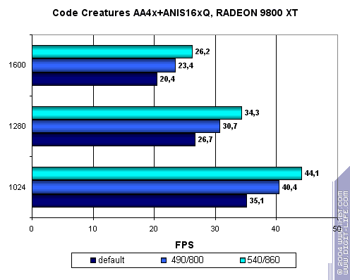
  Code Creatures

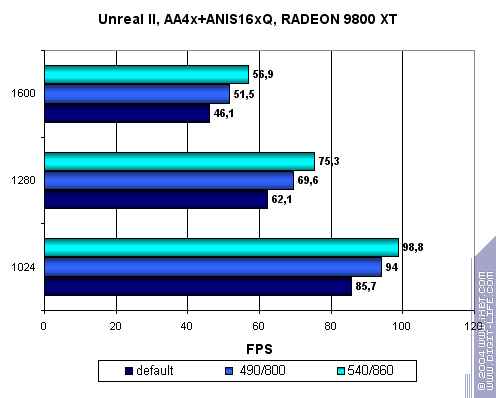
  Unreal II

  3DMark2001SE
 3DMark03
 ConclusionsThe only way to reach high core and memory frequencies is to use the modifications we have described. I don't think enthusiasts will miss the chance to reveal the potential of such a good card. Because they don't forget there's no such thing as redundant megahertzes. Note: the following materials were used to make this article:
Mikhail Ambatiello AKA 2PiZzA (mickey@rbcmail.ru)
26.05.2004
Write a comment below. No registration needed!
|
Platform · Video · Multimedia · Mobile · Other || About us & Privacy policy · Twitter · Facebook Copyright © Byrds Research & Publishing, Ltd., 1997–2011. All rights reserved. |