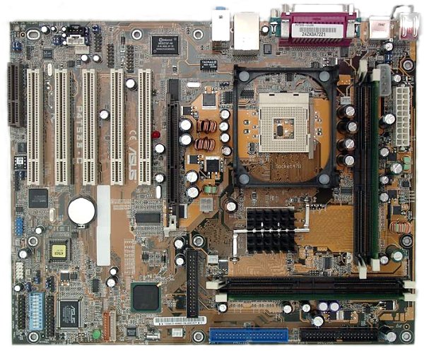
ASUS P4T533-C (i850E) Mainboard
|

The board isn't changed much as compared with the P4T533-E based on
the previous Intel chipset version supporting RDRAM. But this model comes
with the USB 2.0 bus controller; besides, connectors on the rear panel
changed their positions because of additional USB ports. It's interesting
that the user's manual doesn't have anymore a sector on BIOS settings.
Accessories:
-
Package of a standard design;
-
Documentation: user manual in English, brief installation manual in 11
languages;
-
Cables: 1 ATA66/100/133, 1 ATA33 and FDD;
-
Bracket with 2 USB and a Game ports;
-
Bracket for the rear computer panel;
-
2 C-RIMM modules;
-
Sticker showing connectors and switches;
-
CD containing:
-
drivers;
-
ASUS Live Update;
-
ASUS HotKey;
-
ASUS MyLogo;
-
ASUS PCProbe;
-
ASUS Screensaver;
-
Adobe Acrobat Reader;
-
3Deep;
-
CyberLink VideoLive Mail;
-
CyberLink PowerPlayer SE;
-
Winbond Voice Editor;
-
PC-Cillin 2000;
-
DirectX 8.1.

The layout has several typical flaws: audio-ins are in front of PCI
slots, and the FDD connector doesn't allow for handy operation. It's not
difficult to reach jumpers when the board is already installed. Their functions
are shown on the textolite.
The 2-channel switching voltage regulator incorporates 5 capacitors
of 3300 uF and several less capacious ones.
The following controllers are integrated:
-
audio controller based on the chipset's capabilities and Avance Logic ALC650
AC'97 codec supporting 5.1 audio systems and having connectors for front
audio outputs;
-
network controller based on the chipset's capabilities and supporting 10BaseT/100BaseTX;
-
USB 2.0 bus controller based on the NEC D720100AS1 chip; up to 4 ports
supported.
Thanks to the Winbond W83627GF-AW I/O controller the board supports (and
have connectors) readers for smart cards and SD and MS flash cards.
The board incorporates ASUS POST Reporter (reports about problems during
booting), ASUS MyLogo2 (for displaying your images when the system boots),
ASUS EZ Plug (allows using a power unit which doesn't comply with the ATX
2.03 standard), ASUS Q-Fan (auto fan speed control) and ASUS EZ Flash BIOS
(for flashing new BIOS without loading the system from a diskette).
+5 V supplied in the StandBy mode is shown by the green LED, and when
a 3.3V card is inserted into the AGP slot you will see the red LED which
means that the card is incompatible (it's impossible to turn on the computer
even with the Power button).
Non-unsoldered connectors: none.
The system monitoring is supported by the ASUS ASIC AS99127F chip. What
is controlled:
-
processor voltage, +3.3, +5 and +12 V, VBAT and +5 V Standby;
-
speed of 3 fans;
-
temperatures of the processor (a built-in sensor), the board (a built-in
sensor) and an external sensor connected to the board.
There are 3 connectors for adjustable connection of fans.
Brief characteristics of the board: memory slots - 4 RIMM RDRAM;
expansion slots - AGP/ 5 PCI /CNR; I/O ports - 2 COM/ LPT/ 2 PS/2/ 4 USB
1.1 / 4 USB 2.0; dimensions - 305x245 mm.

Adjustment can be carried out with:
| jumpers and switches |
Jumper to clear up the CMOS |
|
| Jumoper for setting the JumperFree mode |
Enable/Disable |
| Jumpers to choose a FSB frequency |
100, 103, 105, 110, 133, 136, 138 and 140 MHz |
| Switches for setting processor's multiplier |
x12-x24 |
| Jumper for starting up computer from PS/2 keyboard |
|
| Jumpers for starting up computer from USB keyboard |
|
| Jumper to enable/disable the USB 2.0 controller |
|
| Jumper for increasing the processor's power by 0.1
V |
|
| Jumper for choosing a mode of the Bass/Center channel |
Bass/Center / Center/Bass |
| Jumper for setting the sound output device |
Buzzer/ Line Out |
| BIOS based on the 6.00 version from Award |
Setup of memory timings |
+ |
RDRAM Turbo Mode |
| Setup of memory frequency |
+ |
at FSB 100 MHz: Auto, PC600 andPC800;
at FSB 133 MHz: Auto, PC800 and PC1066 |
| Setup of AGP bus |
+ |
|
| Setup of PCI bus |
+ |
|
| Changeable scaler of AGP and PCI buses |
- |
|
| Manual assignment of interrupts |
+ |
|
| Changeable FSB frequency |
+ |
100, 103, 105, 108, 110, 112, 115, 118, 120, 122, 125, 130, 133,
136, 138, 140, 142, 144, 145, 148 and 150 MHz |
| Changeable CPU multiplier |
+ |
x8-x50 |
| Changeable core voltage |
+ |
1.1-1.85 V in 0.025V steps |
| Changeable memory voltage |
- |
|
| Changeable chipset voltage |
- |
|
| Changeable AGP bus voltage |
- |
|
We used the latest available version of the BIOS - 1007 beta 002.
The board is rather pleasant, the only drawback is its price which,
however, won't be a surprise for those who assemble a top computer based
on the top processor Pentium 4.
Test results:
Write a comment below. No registration needed!
|
|
 |
|
|
|