|
||
|
||
| ||
|
||
|
||
| ||
Some 20 years ago there was no real alternative to silver in the photoprocess. It provoked gloomy estimates that soon all silver resources would be on the exposed paper and photographic films, and there would be no silver for new snapshots. When colour photography started to blossom and centralised photolabs gained popularity, the problem ceased to be so acute. There was no more silver left in the ultimate print and all the silver from the process could be gathered and used for making new photographic materials. Today the silver monopoly is significantly undermined. Electronic films (matrices) have almost as much registered details per area unit as conventional ones (400 sensitive elements per mm). A theoretical wave-length limit is not a long way off either, that is why we can hardly expect a considerable increase in the number of details per area unit. Thus, the electronic film issue may be considered solved, and the revloution dreamed of for the last 100 years has occurred: there is an alternative to silver. Of course, it is easier to produce argentiferous photomaterials than matrices, as the former can be custom-made even at home. But the last 100 years saw very few photographers who made materials themselves, and it can be said that there is a standard registering material available everywhere. So we can concentrate on constructing cameras. The photography history has had much more construction types than types of photomaterials. Successful camera models were made by both huge companies and individual artisans, taking into account that the camera proper has a much longer history than silver photography and dates back to the pinhole camera. The first lensed pinhole camera with was probably made by Giloramo Cardano in the 16th century, and contemporary digital camera developers should pay more attention to the centuries-long history. Probably, there have been a lot of really good solutions turned down due to purely subjective reasons. For example, they could have been rejected because compact camera were trendy then, or because picture quality exceeded the needs and thus, wasn't a decisive criterion for the camera choice. In my opinion, there are too many myths now about which solutions are suitable for camera constructing and which are not. It gives me the impression that many contemporary constructors try to "reinvent the wheel", while they can use engineer solutions of 10 or even 100 years ago. They often come up with new standards, although the current ones are still up to the mark. Apart from that, I believe things are worsened by an inappropriate patent system that not always fixes the inventor's name for history, helps little to a sooner introduction of the invention, and consumes considerable human resources. Nowadays, each engineer "feeds" two patent engineers and four lawyers. Besides, holders of rights, in contrast to inventors, often have their own interest in causing impediments for the invention to be produced. Usually an author's biggest dream is to see his idea carried into life. Today chances are that his invention will be shelved, and other constructors who, by chance, have came up with the same idea will face insurmountable, deliberately created impediments for its realisation. Besides, inventors can't really count on high salaries, it is the holders of rights that get huge profits. Actually, the whole patent history is full of such blatant inconsistencies. As an example, let's look up radio inventions in a seemingly neutral source, the French Larousse encyclopedia. This is what it says in the Science and Technology chronological chart, chapter Technology: "1893, radioantenna, Popov (Russia). 1896, radio communication, Marconi (Italy)". Isn't it a bit inconsistent? Camera ConstructionIn this chapter, I'll try to refute a number of actual stereotypes concerning photography and also to tell you about well-known technical solutions that can, in my opinion, be applied to digital photography. From the very beginning, the camera has been a block device and everyone could assemble it in his own way, so the problem of standards has always been very acute. The camera can roughly be divided into the following main blocks: light-sensitive material, lens, focusing system, and shutter that ensures a set exposition time. The last straw that made me construct my own camera was the announced Four Thirds standard. This standard clearly specified the frame size, but up to the moment I was finishing this article I haven't found any Internet information on the baseline length, or any bayonet drawings. Any standard implies some specs basing on which one can make compatible devices. I haven't found any specs for bayonet mounts in the 4/3-compatible devices. I guess the standard combines two independable things: a bayonet mount does not necessarily have any connection with the image field and the frame size. Light-sensitive material
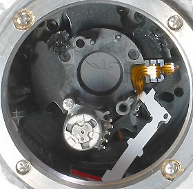
Today's matrices probably have a larger circulation than films a 100 years ago considering the number of frames they can make, and a frame costs no more than those days. Matrices are produced by several manufacturers in an almost ready-to-use form, including all the logics necessary for their functioning. I think, today it is easier to make a viable electronic scheme with a matrix than it was to make a transistor receiver 40 years ago. Much has been said about an allegedly inappropriate matrix size, and that matrices can't be used if their area if much smaller than the operable field of the lens. However, it has always been like this, and the same cameras with the same lenses used 18x24, 13x18, and 9x12 plates. Many middle-format cameras allow to make snapshots of 4,5x6, 6x6, 6x7, 6x9 formats (see this article). The Contax company advises that custom-made cameras with a 24x36-mm frame format should be used with model 645 lenses designed for 6x4,5 frames. Even frames of a 35-mm film can not only be 24x36. There were many cameras made with 24x18 frames (Chaika, Zorky-12, FED-Micron, Agat-18), and Nikon 1 had frames with a 24x32 format. It is not at all bad that the area of a light-sensitive element is smaller than the lens's workspace. The whole area hasn't been used since the daguerreotype era. If we want to register everything the lens has created, we'll get a round frame. If a frame is much smaller than the image field, we can easily move it thus making up for perspective distortions. See this article for details. Another problem that arises when using a large-area matrix with short back focus lenses is sunbeams falling on the frame edge. Most matrices have a special filter before them, that doesn't let ultraviolet and infrared areas of the spectrum pass. It is a parallel-sided plate several millimeters thick, that can considerably displace and reflect a substantial share of edge rays. Concerning this type of camera, it would be better, perhaps, to remove the filter from before the matrix and to place it before the lens, as it was in the first Kodak DCS cameras. But then its area must be much larger, and hence, its cost will increase dramatically. Bayonet mountsWhen a device is being projected, developers always have to think about its compatibility with the previous devices of the same type. About a hundred years ago, a curious device similar to the iris aperture was invented, that enabled to fix lenses with any kind of thread. Also very popular was the idea to use one big aperture and a lot of mount adapter rings for smaller diameters.  A universal lens ring. A drawing from the "Pocket guide on photography" by E. Fogel, 1928. I'm convinced there's no need to reinvent the wheel if you can use the existing standards. The following thread standards are well-known and aren't patented: M39 with a 28.8 mm baseline, M42 with a 45.5 mm baseline, bayonet joints K and recently M (since the time its patent has expired). The shorter the baseline is, the more lenses can be fixed to the camera with the help of appropriate adapters. The thread-to-thread adapter is easy to make (you only need a lathe for it), and the thread-to-bayonet adapter is simpler than bayonet-to-bayonet, so I suggest we go back to the M39 standard. To all appearance, lenses of movie cameras with a shorter baseline will be also possible to fix if we use a barrel-shaped adapter, as the lens mounts of these lenses are usually under 30 mm. Of course, bayonet joints enable a quicker lens-fixing, but first, most lenses are expected to be fixed with adapters, and second, I hope that given the elapsed time, you have less chances to be involved in a lawsuit concerning M39, as was the case with the K-M42 adapter (for details click here). The moral is, if you want your invention to be shelved, patent it. In 99 cases out of 100 it won't bring you any money, but your dog-in-the-manger image will be bright in the minds of those who will have invented a similar device later. Unfortunately, inventing is not a "vein of gold", and the fact that you were the first to reach the finish line doesn't mean others can't do it too. The contemporary patent system doesn't remember the inventor's name, just the name of company that pays salaries. Customers can't be restrained either: a sale contract and a lease contract are different things. So, if I buy a microscope for nailing, it's my choice, and I can modify it to my own convenience. And that reminds me of a piece of news we recently had about a curious trial in Italy. Modern lenses have not only a mechanical, but also an electrical fixation to cameras. Info transmission contacts can be made as sockets for plugs. The idea looks as follows: signals to contacts 0 and 1 (with an appropriate load current, so that they can be used for analog controlling); contacts: lens move forward, lens move backward, open the shutter, close the shutter (that's a bit redundant, but you can use only one contact), synchronise the flash, close the aperture, aperture value - 4 contacts (16 values should be enough, but a fifth contact can also be added), change focal length - 2 contacts, contacts for back lens-camera info transmission: focal length, distance (probably, a 3-wire serial port should be used). So, the simplest case for using lenses with instant-return apertures is: to fix the aperture onto the lens, and make amendment to the exposition, corresponding to aperture stops. Focusing and exposition measurement is done with a fully open lens; shutter release pressing sends a signal to the adapter ring, the core sinks into the solenoid and pushes the aperture rod (see also the scheme at the end of the article). FocusingHistorically, focusing could be done by moving either the lens or the light-sensitive plate. Initially, the latter variant was mostly used, but the former proved to be simpler in construction and became the main way when transition to films took place. But don't think the lens-moving construction wasn't used in film cameras. In fact, it was. Focusing also implies a lens skew from the sensitive material. It was widely used in first cameras, but almost completely given up later. Partially because visual matte screen focusing did not ensure immediacy, and rangefinder cameras could only focus on one point. A better focusing was in many cases achieved with the help of a precision distance scale on the mount of a well adjusted lens, and using tape-line was the most precise way to measure the distance to an object. Reflex cameras were better in the way that a precise adjusting of the film channel and the matte screen allowed you not to think about a precise baseline length of the lens. If the image is sharp on the matte screen, it will be sharp on the film as well. But in my opinion, reflex digital cameras have an illogical construction: why focus by an additional matte screen if we can focus by the image on the LCD? Modern LCD quality is quite comparable to a coarse-grain matte screen, and today's technologies enable to produce LCDs that are not at all inferior to the best matte displays. Then autofocusing appeared. It was basically realised by a separate motor in each lens and sometimes by the camera motor that moved the lens, as in Pentax cameras. The most interesting cameras of all that enabled to work with standard lenses is Contax AX (1996?). In it, almost all the inside is moved about the lens. Here is a scheme from an advertisement. 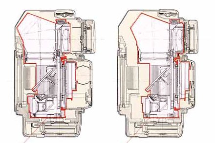 It's a pity that there's not a single word about this camera on the Contax web-site. Probably the most interesting camera didn't even get into the official history. Some other sites contain the company's press release that tells a history of this camera creation. It's inconvenient to move the film as it occupies much more place than the gate aperture, and can have a significant weight with a transportation mechanism. Today's matrices are not much larger than the gate aperture and are a lot lighter compared to the lens. Moving matrices seems to be a quite logical solution, and it was, in fact, realised in many scanners. Then came autofocusing by multiple points. But if a plane can be drawn through three points why have more for autofocusing? Probably because only three points are used from the whole multitude each time. But in today's reality the plane is not skewed, that is only one focusing point is used. Matrices weigh far less than lenses, and they are easier to move. And since we have several focusing points, it would be logical to skew the matrix, not only to move it. With three focusing points and three motors we can get an autofocusing system about as functional as century-old road cameras. ShutterConstructions and scheme of shutters are thoroughly described in this article. In principle, the shutter mustn't necessarily be part of the camera, it can as well be an external element (such as an lens lid) or an element embedded into the lens. And the camera should have a controlling device for an external shutter. Ideally, there should be two shutters in the camera (as some middle-format cameras have). A focal one would be placed right before the sensitive element, that works in case the lens has no central shutter of its own; and a central one would be embedded into the lens. Shutter's functions also include flash synchronization. For more details see this article. What and How Has Been DoneLet us take a look at how a module digital camera can be custom-made at home. I'm warning you in advance that if you have problems disassembling an operable camera and keeping it operable after reassembling, you may as well have problems transforming it. In principle, anyone can learn to disassemble cameras, but the number of ruined cameras in the course of learning depends on each particular individual. I'm not going to tell you about the screws that hold the case, as it will be a test of your abilities. But I'm definitely going to mention that you won't do without a soldering-iron: some cords are just too short. And apart from the screws, the case is also held by clips that really take some effort to unfasten :-( The Casio QV 3000 camera forms the basis. You can see it disassemled here. And that's the unit that joins the lens, the matrix, and the viewfinder: 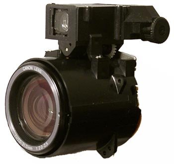 The unit is practically the same in the following cameras: Casio QV3000, QV3500, QV4000, QV 5700, Canon G1, G2, Sony S70, S75, S85, Toshiba PDR-M70. 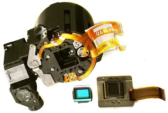 The lens unit was completely disassembled. The following parts were removed: the viewfinder, all lens lenses, motors for changing focal distance and focusing. That's what the motors look like: 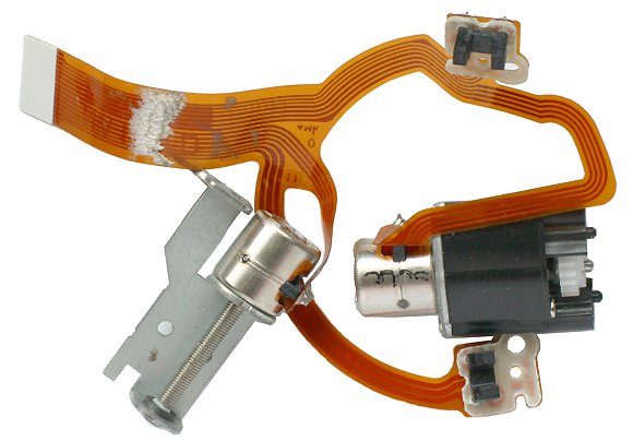 On the left: the motor that moves the lens at focusing
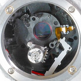
It turned out that after we turned off the loop to the motors and end switches the camera continued to be operable and didn't respond to the removal of the lens. The central shutter was taken out of the lens, turned to 180°, and placed before the IR-filter that rests against the matrix.
In this camera, the central shutter has two functions: to limit the exposition time and to measure the aperture diameter. We are not going to use the second function, and the only thing that's important for us here is to have a camera capable of fixing the aperture in the fully open position, and to have a diameter longer than the matrix diagonal. That is, a camera is deemed fit for transformation if its exposition and aperture can be controlled manually and if the maximal aperture diameter, roughly measured as the lens's maximal focal distance divided by the f number, is longer than the matrix diagonal. Casio QV 3000 has a Sony ICX 252 CMOS matrix. Its dimensions are 7.2 x 5.35 mm, which makes its diagonal about 9 mm. The lens's maximal focal distance is 21 mm, the maximal f number is 2. So, the aperture diameter must be longer than the matrix diagonal. In reality, the lens speed at a bit lower at the maximal focal distance, and to avoid corner vignetting one has to be very precise in superimposing the shutter aperture on the matrix. Thus, we turn the central shutter into the focal one. But in contrast to classical focal shutters with the blinds moving from one end of the frame to the other, this one has blinds moving from the centre to the end. However, it turned out that at expositions longer than 1/400th second, blinds move so fast that superfluous frame-centre exposition is not visible. In general, if a camera has a B exposition, one can use the central shutter embedded in the lens.
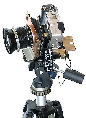
It turned out that even if we rid the camera case of the jut surrounding the lens, the distance between the front wall and the matrix will exceed 28.8 mm. Thus, in order to use an M39-threading bayonet mount taken from Zorky-5, we had to displace the barrel with the matrix by about 5 mm closer to the camera wall. For this purpose, supports were sawn off and the lens barrel was shortened. Of course, it would be better to make a new mount, but this construction has a barrel of the lens case that has been moved forward, rigidly joined with the camera case, and supplied with a Zorky-5 M39-threading ring screwed to it. In order to get a precise adjusting, I used a Jupiter-3 lens focused to infinity, and reached a sharp image by placing washers under the bearing ring. An M39-M42 adapter was made to work with lenses for reflex Zenit-like cameras. It consisted of two extension rings with washers in between to make the ring exactly 16.7 mm thick. With everything made precisely as it has to be, the lens scale will be enough for a satisfactory focusing on most objects. Digital cameras have the advantage of displaying exactly the same image that is projected upon the matrix. In contrast to film cameras, they don't need the complex processes of mirror lifting and matte screen adjusting. But there's a rub here, as only each fortieth registered pixel is shown on the display. However, the ratio between silver crystal dimensions and matte screen grains is no better. The test shooting showed that acceptable focusing quality could be achieved in all the cases. They often say that lenses made for film cameras have the resolution of 50 line pairs per mm, that is matrices with the 640x480-pixels frame size will be the most effective with them. But they forget that lens specs are given for the aperture opened at maximum. These lenses, such as Jupiter-3, have a 1:1.5 relative aperture. And its resolution will substantially improve at the aperture of 1:5.6 (typical of most point-and-shoots with long-focus lenses). But with a matrix like this, a 50-mm lens is similar to a 250-mm lens of a 35-mm camera in terms of viewing angle, which is what most point-and-shoots can only dream about. As for diffraction, it only makes difference at apertures below 1:11. That is, with a proper apertureing, this lens can really ensure a resolution that will fully realise matrix capabilities. Partially it will be possible due to the fact that only the central part of the image circle is used. Camera transformation enabled to separate the influence on the lens and matrix sharpnesses. Below are the results of shooting made with one and the same lens (Gelios 44). The matrices are ICX252 and the one from the Canon D60 camera, their sensitive elements are almost twice different in size. 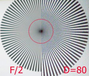 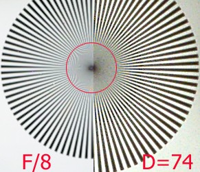 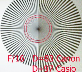 Canon is on the left, Casio is on the right. The image was zoomed in twofold for a better view. The letter D stands for the diameter of the blur circle, in pixels. Adjacent strokes inside the circle are not discernible: they are either absent or very much distorted. The lens's focal distance is 58 mm. The test-object has 90 radial black strokes.
At the F/8 aperture, the lines per pixel resolution is the same for different-size pixels, therefore the lens resolution exceeds both matrices' capabilities. At F/16 and F/2, resolution for ICX 252 is determined by the lens, while the Canon-Gelios system has but a slight lens's influence. Let us take a closer look at the resolution dependance of the Gelious 44 - ICX 252 system:  Maximal contrast and resolution at F/8-F/11; abberations are clearly visible at F/2, F/16 gives a decrease in contrast and resolution.
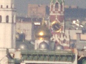
What has become of itUsing removable lenses not only allows to change lenses, it also enables to advance the lens considerably at macroshooting, to tilt the lens for a sharper image of the plane that is not perpendicular to the optical axis, to move the lens to make up for perspective distortions, and finally, to use a microscope instead of the lens. A small matrix (compared to a 35-mm frame) allows us to move and tilt the lens without a considerable loss in quality. The newly-made camera is designed for special shootings, in the first place. Using a Rubinar-500 lens we can get a sharp picture of the Moon with the size of a whole 3Mp frame. And if we also use a TK-2 teleconverter, only part of the Moon surface will be in the frame.  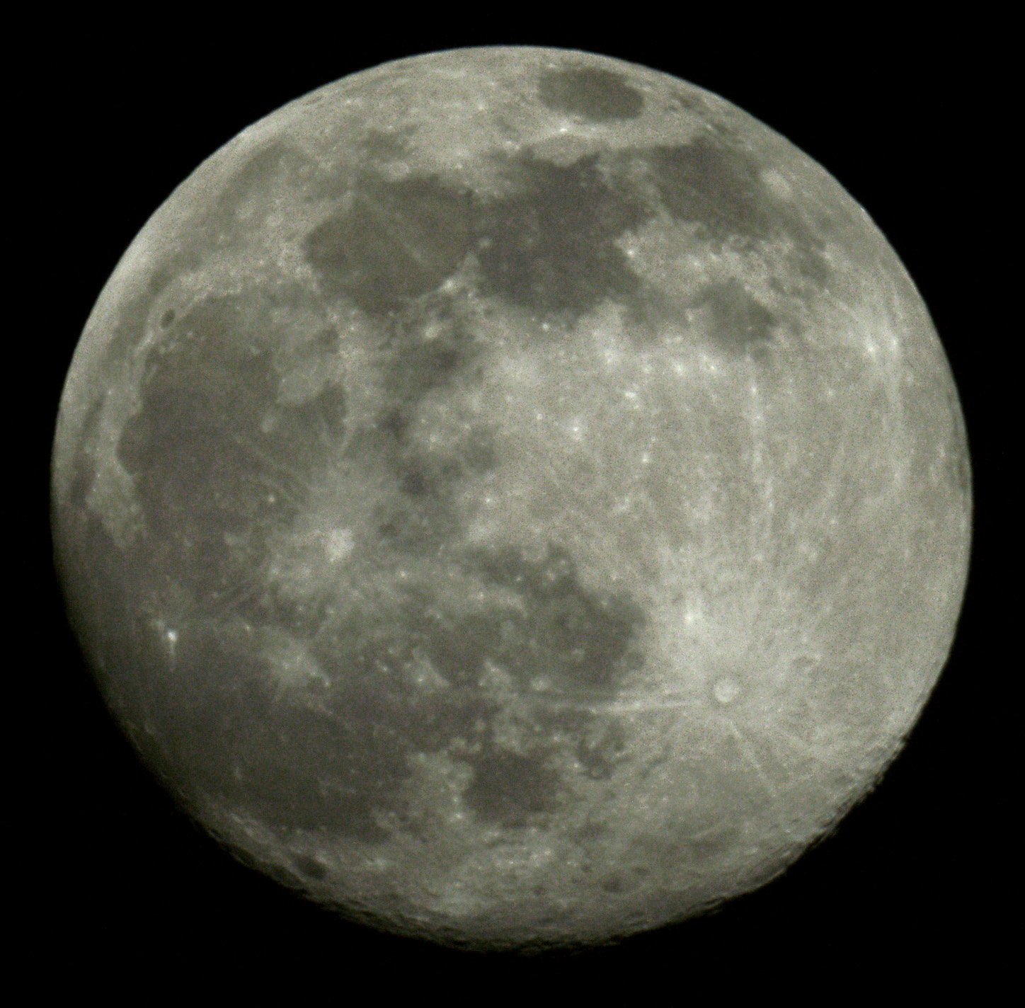 You can see a maximal-size image by clicking on the picture.
For comparison purposes, we took pictures from one and the same point using different lenses. You'll see a small picture and a frame fragment for each of the lenses.
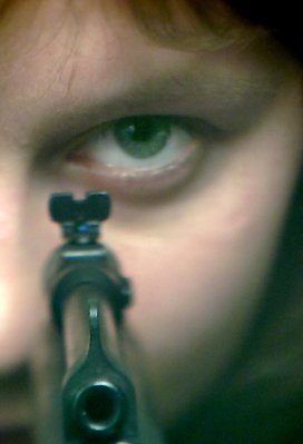
A Pentacon 135 lens makes a splendid camera gun. We recommend to use a shaft with a loupe before the LCD and a monopode resting against the photographer's belt (click here for details). We have a focal distance equal to 650 mm in a 35-mm camera. And besides, it is no more difficult to focus by a LCD than in a reflex camera. 
Jupiter-3, focal distance is 50 mm. 
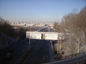
Because of its extraordinary 1:1.5 lens speed, we decided to try it for portrait-shooting with a fully open aperture. This is what we've got:  As Jupiter-3 is the only M39-threading lens, we'll show you one more landscape snapshot.  Click on the two pictures above to see their actural sizes.
You can also use wide-angle lenses with this camera. Such as a 16-mm Zenitar:
An 8-mm Peleng:
In this case, you are unlikely to have a better quality than using the original lens, but still, you can get a focal distance close to that of the original model. If focusing is on the plane perpendicular to the optical axis, you don't necessarily have to focus by the LCD, the lens scale will do for setting the distance. Considering all this, it is advisable to shoot at F/11. The depth resolution at apertureing allows to get perfect landscape shots using nothing but the distance scale. Click here to see another series of shots taken from one point with different objectives. If you tilt the lens you'll have to look more thoroughly into the LCD.
But then you can, for instance, get a sharp image of a keyboard in an unusual perspective:  Or to show some brooch details that would be behind the stones if shot full face.  You can distinctly see that the background plane is not perpendicular to the optical axis, but its whole length is in focus.
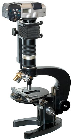
With a microscope attached, the system showed excellent results with a magnifying not worse than digital reflective cameras give. And focusing proved to be much more handy by a display image than by the opal glass.
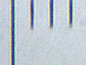
 A fragment of Anabaena sp. thread. So, do we have a new camera or just a modified one? That's a point at issue. If we draw an analogy to the difference between a FED and a Zenit, then we have changed more elements of the construction. Thus, we are entitled to say that we have created a new camera based on some other model. What we wanted to doIf we have boxed CPUs for our computers, we'd also like to have boxed matrices and motherboards for our cameras, wouldn't we? The rest is optional. Many actual cameras have a 3-wire serial port so we can connect a computer and control the camera through it, we can connect a remote controller and keep it on the cable or embed it into the camera. There is a TV output for image displaying, and there is USB for data transmission. More advanced models could even have a card-reader and an LCD. Both the TV output and the serial port are a sort of a tribute to the past. A USB will be quite enough for controlling the camera, transmitting the image to the computer or PDA at pointing and focusing, and storing the shots. A PDA as a universal controller and viewfinder was realised in Leaf valeo 11 and described in the article. Since focusing points can be moved and there can be several of them, the matrix should be fixed on the platform moved by three worm-gear motors, like in the Casio we dismantled. We only need to fix three identical motor-control units on the motherboard and to provide them with the three focusing points, and then, like a hundred years ago, we'll be able to focus not only by the plane perpendicular to the optical axis. Since many lenses have a field much larger than the matrix size, the possibility of shifting would be very much to the point, as would be a matrix stabilisation system similar to that used in Minolta A1. I represented all my thoughts as an animated interactive scheme: The green button activates an autofocusing, its functions are similar to those invoked by half-pressing the release button of modern cameras. The orange one releases the shutter; if the camera is not focused, pressing the button involves focusing and only then a shutter release. Small buttons control presentation: the upper one runs the film from the very beginning, the lower one stops the viewing in the position that corresponds to infinity focusing. On the prospects
The camera described here was first announced in the Internet on February, 17th. On March, 11th, Epson released its Rangefinder Digital Camera R-D1. Although it can hardly be called Epson — it looks every inch Cosina's Bessa. But then again, the press release mentions cooperation between Epson and Cosina. It is a classical rangefinder camera, with a Leica M bayonet and a Leica M - Leica L (that is, M39) adapter ring. The camera also has an APS-format 6Mp matrix. I think the use of an old thread standard for rangefinder and viewfinder cameras certainly has good prospects. This way we can use all optics for both rangefinder and reflex cameras. Moreover, considering the difference in the baseline lengths, we can make electronic-fitted adapters that will enable us to use autofocusing lenses and lenses with an automatically controlled aperture and an embedded shutter. These adapters will function if we supply the camera case with a number of signals in the form of plug connectors. And it would be even better if users were able to program the signals themselves. The idea to enable users to program cameras seems very interesting, and it's a pity Kodak's undertakings realised in DC265-type cameras remained undeveloped. On the other hand, I don't believe rangefinder cameras have a good outlook. In my opinion, it makes much more sense to assemble a viewfinder camera with the distance to the object being set by the scale. The rangefinder can be added separately, a lot of them have been produced, for instance Blik. A rangefinder coupled with the lens is convenient, but it only works with certain lenses. Of course, we can make it compatible with almost any lens, but do we really need it? It would be much more sensible, I think, to make an autofocusing system similar to Contax AX. Because in this case we don't need to move a film with cassettes, but just a lightweight matrix. Modern autofocusing systems can focus by multiple points, but without matrix skew a precise focusing can only be achieved by one of them. Thus, I think, it's more sensible to use three identical worm-gear motors, similar to those used in Casio QV 3000. In this case, if the motors are run synchronically they will ensure focusing on the plane perpendicular to the optical axis. If the motors work separately, they will allow autofocusing comparable to manual focusing in studio cameras.
Writer: Vladimir Rodionov (rwpbb@ixbt.com; Russian language only)
Translator: Vladislav Pikalov (peek@ixbt.com) Original article link: http://www.ixbt.com/digimage/m39var1.shtml 20.04.2004 Write a comment below. No registration needed!
|
Platform · Video · Multimedia · Mobile · Other || About us & Privacy policy · Twitter · Facebook Copyright © Byrds Research & Publishing, Ltd., 1997–2011. All rights reserved. | |||||||||||||||||||||||||||||||||||||||||||||||||||||||||||||||||||||||||||||||||||||||||||||||||||||||||||||||||||||||||||||||||||||||||||