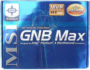
MSI GNB
Max-FISR - (Intel E7205) Based Mainboard
|

The board has almost all controllers typical of modern boards as well as excellent
functions and a good accessory pack. In the tests we used a preproduction sample.
Accessories: - Package of the standard design;
-
Documentation: user manual, installation manual for IDE RAID, computer buildup
manual - in English;
- Cables: 2 Serial ATA, 1 ATA66/100/133 and
FDD;
- S-Bracket (Rear, Center/Sub and S/PDIF-Out connectors (Coaxial
and TosLink));
- D-Bracket (2 USB + 4 LEDs monitoring the POST procedure);
-
Bracket for the rear computer panel;
- Diskette with drivers for
IDE RAID;
- 2 CDs containing:
- drivers;
-
DirectX 8.1;
- Adobe Acrobat Reader;
- VNC;
-
3Deep;
- PC-Cillin 2000;
- X-Setup;
- MSI
DVD;
- MSI Fuzzy Logic (for auto processor overclocking);
-
MSI GoodMem (for memory optimization);
- MSI InfoView (information
on system devices);
- MSI i-Speeder (optimization of the Internet
access and monitoring of network connection);
- MSI Live Update 2
(for automatic update of drivers and BIOS);
- MSI LockBox (to lock
access to the computer);
- MSI Password Keeper (to store passwords);
-
MSI PCAlert IV (for system monitoring);
- MSI SecureDoc (for file
encryption);
- MSI SmartKey (for operation with SmartKey).

The layout has typical drawbacks: audio-ins are in front of the PCI, and the
IDE RAID are behind them; some connectors on the left edge are not in very good
positions. It's not difficult to reach the only jumper when the board is already
installed. Its functions are shown on the textolite. The 2-channel switching
voltage regulator incorporates 7 capacitors of 2200 uF and 7 of 1500 uF.
The following controllers are integrated: - audio controller
based on the chipset's capabilities and C-Media CMI8738/PCI-6ch-MX chip supporting
5.1 audio systems and having a connector for front audio-outs and for S-Bracket;
-
network controller based on the Intel RC82540EM chip and supporting 10BaseT/100BaseTX/1000BaseT
(Gigabit Ethernet);

-
IDE RAID controller based on the Promise PDC20376 chip supporting RAID 0 and 1
on the ATA133 and SATA 150 protocols;
- IEEE 1394 bus controller
based on the VIA VT6306 chip.
Non-unsoldered connectors: none.
The system monitoring is supported by the Winbond W83627HF-AW chip. What is
controlled: - processor voltage, +3.3, +-5 and +-12 V, VBAT and +5
V Standby
- speed of 2 fans;
- temperatures of the processor
(a built-in sensor) and the board (a built-in sensor).
There are
2 connectors for adjustable and 1 for unadjustable connection of fans (it's connected
to the fan on the heatsink of the chipset's north bridge). Brief characteristics
of the board: memory slots - 4 DDR SDRAM; expansion slots - AGP Pro/ 5 PCI;
I/O ports - 2 COM/ LPT/ 2 PS/2/ 6 USB 2.0 / 3 IEEE1394; dimensions - 305x247 mm.

Adjustment
can be carried out with:
| jumpers and switches |
Jumper to clear up the CMOS |
|
| BIOS based on the 6.00PG Award WorkstationBIOS from
Phoenix |
Setup of memory timings |
+ |
CAS Latency, Active to Precharge Delay, RAS to CAS Delay, RAS
Precharge |
| Setup of memory frequency |
- |
|
| Setup of AGP bus |
- |
|
| Setup of PCI bus |
- |
|
| Changeable scaler of AGP and PCI buses |
- |
|
| Manual assignment of interrupts |
- |
|
| Changeable FSB frequency |
+ |
100-200 MHz in 1MHz and 2 MHz steps |
| Changeable CPU multiplier |
+ |
x8-x32 |
| Changeable core voltage |
+ |
1.1-1.8 V in 0.025V steps |
| Changeable memory voltage |
- |
|
| Changeable chipset voltage |
- |
|
| Changeable AGP bus voltage |
- |
|
We used the BIOS 2.0 as the latest available version.
A high functional level go along with a lacking total control over the system
from BIOS. So, this is a good though quite expensive base for an efficient workstation.
Write a comment below. No registration needed!
|
|


