 |
||
|
||
| ||
|
||
|
||
| ||
The problem of effective cooling of high-performance computer systems has been on everybody's lips for a long time already and it adds troubles both for experts, enthusiasts and average users. The situation is aggravated by the fact that many PC assemblers simply "ignore" (probably for the sake of a higher income) a complex approach to cooling of a whole computer system: most part of produced computers are pressed into too tight and hot boxes deprived of any effective means of internal ventilation. It's not crucial for budget systems, but correct and reliable operation of a high-performance computer filling in such conditions is questionable. Last time we took a deep look at operation of fans and their key technical parameters. Today we are coming back to these devices: we are going to use their performance curves in practice and look at the ways of objective estimation of effectiveness of cooling devices for computer cases. Initial conditionsApart from arranging internal components and satisfying users' aesthetic needs every system enclosure is in change of efficient removal of heat generated by the filling, including a power supply unit. Almost every computer component requires its own climatic conditions. The most severe requirements come from modern processors of Intel and AMD: the air temperature on the "input" of a fan of a processor's cooler mustn't exceed 35-40°C. Other components (mainboard, video card, hard drives, DVD-ROM/CD-RW drives etc.) are less exacting, but they all are in the same "hold" and willingly support desires of the latter.The problem of maintaning the optimal internal temperature gets harder to tackle: the overall heat "capacity" of computers keeps on growing (heat development of modern complex systems on the Athlon XP or Pentium 4 can reach 250-300 W), and no steps of thermal optimization of typical configurations of ATX cases can be noticed. Some advanced users try to optimize cooling systems themselves using the cut-and-try method which not always brings desirable results. However, there is a simper and much more reliable technique that allows us to estimate objectively effectiveness of a given cooling system and, if necessary, to optimize the system or get a new better system enclosure. This technique is based on a simple semiempirical formula
Ti - temperature inside the system enclosure, To - temperature on the input of the box (ambient, indoors temperature), Q - performance of the complex cooling system. This correlation shows what performance a cooling system must have to remove required thermal power at given temperatures inside and outside a computer unit. Note that it accounts only for convective heat transfer (i.e. with an air flow). Other types of heat transfer - thermal conductivity (i.e. via contacts of internal devices and panels of the enclosure) and radiant heat exchange (via electromagnetic radiation) are not taken into account. However, these two types do not have a noticeable contribution (it doesn't exceed 2-5% of the overall heat development), that is why P can be considered an entire thermal power of a system. Well, let's take an average statistical configuration of a high-performance
computer, write down values of thermal power developed by its components
and put them into the Table 1.
So, let's set the "input" temperature equal to 25°C and the desirable internal temperature to 35°. The sought value of performance of a cooling system is approximately equal to 35 CFM. If you are going to put all components into a fan-less case, 25-30 CFM as a rated performance of the internal fan of the power supply unit will be the maximum that can be reached, which is still not enough for the comfortable conditions. Besides, as we found out last time, real performance of a fan in certain conditions is much lower than the rated one. As a result, we can face a problem of impossible maintenance of either comfortable internal temperature or even a permissible one. System impedanceSystem impedance is used for quantitative description of resistive effect a given computer system and its components have on an air flow. This aerodynamic characteristic is based on the following formula:
Q - fan performance, n - turbulent factor (1 <= n <=2, n = 1 in case of a laminar flow regime, n = 2 in case of a turbulent flow), P - system impedance. System impedance is calculated in mm or inches of water (like static pressure) and shows pressure of an air flow at a given volume rate in a given system. An exact shape of an impedance curve can be found only in lab conditions, with a defined system constant and turbulent factor. But in most cases this can be brought to a linear dependence
The system impedance is important from the practical standpoint: if you draw the impedance curve using experimental or reference data and superpose it with a characteristic curve of a fan you can define a real performance of the fan in a given system. Let's take as an example the IN-WIN IW-S508 case (without additional fans), put in here the above mentioned configuration based on the Athlon XP and install the CWT-420ATX12 power supply unit with a non-standard powerful fan ADDA AD0812HB-A70GL rotating at 3100 rpm. The impedance of such system can be expressed as P = 0.085*Q. Now let's draw a final system impedance curve and superpose it with the fan's performance curve to get a working point of the fan, i.e. its real performance in these conditions. 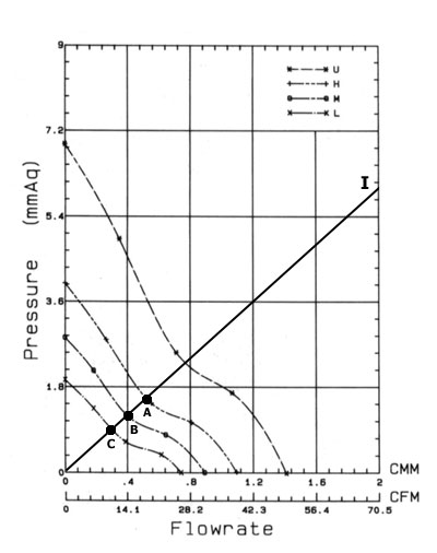 Figure 1 System impedance, fan's performance curves and working points So, a typical fanless enclosure can't serve as a comfortable house for a high-performance computer system. The upper limit for such cases is 100-115 W of thermal power which usually corresponds to heat generated by budget or highly integrated systems used for office tasks. For systems that generate over 115 W fanless enclosures are not a match, they are even dangerous. Attention. The above things concerned top rear mounted power supply cases (TRMPS). Core logic mounted power supply cases (CLMPS) usually have a higher system impedance. Therefore, the actual performance of fans in the CLMPS cases will be lower. The maximum thermal power such cases are able to cope with is within 75-100 W. Be careful! So, what should we do to provide the required climatic conditions for the computer stuffing? The way out is just one - take a system enclosure equipped with additional cooling devices. Additional fansA wide range of system enclosures have special seats for fans on the front/rear panels. As we found out, a standard fan installed into a power supply unit is sufficient to remove only 115 W of thermal power. But with a hotter system we can't do without additional coolers. Well, they are installed right in the above mentioned seats.Will such fans be able to become an effective cooling complex and provide acceptable climatic conditions for computer components? Let's see! We are using again the IW-S508 case and the Athlon XP based system, plus one additional fan (the same ADDA AD0812HB-A70GL) into an appropriate seat on the rear panel. Here is Figure 2. 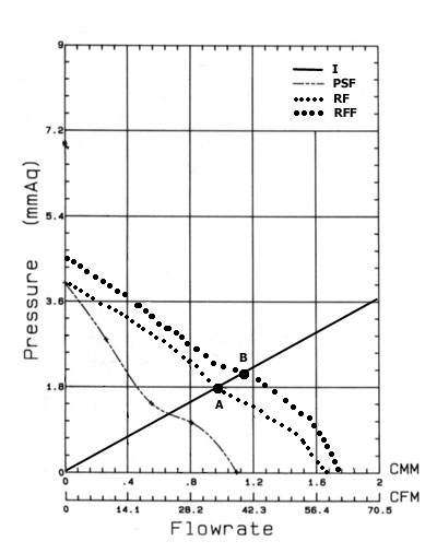 Fig 2. Performance curves of different complex cooling systems What brings the rear fan? First of all, at the expense of redistribution of air flows inside the case the overall system impedance falls down considerably, now we can write it down as P = 0.054*Q (curve I on fig.2). Secondly, the average volume air flowrate gets much higher (curve RF demonstrates the total performance of the power supply unit's fan and the additional fan). Thus, the actual performance of the general cooling system reaches 33-34 CFM (point A), which is very close to the required 35 CFM and enough to maintain a comfortable internal temperature. Now let's see if we add one more fan onto the front panel. Unfortunately, it doesn't bring much benefit. The impedance of the system remains the same (even a little bit greater), the overall performance of the cooling complex consisting of three fans (one in the power supply unit and two inside the case) grows up by just 4-5 CFM (fig.2, curve RFF and point B, the impedance curve is the same). So, the behavior of our system shows that the rear fan of the rated performance of 39 CFM and an impeller's speed of 3000 rpm is a necessary and sufficient condition for effective removal of 200 W of heat and for maintaining the internal temperature within 35°C. One more fan installed onto the front panel and having the same characteristics provides an insignificant performance boost for the cooling complex, which is even unnecessary. But power supply units of ordinary system enclosures come with rather weak fans, that is why an actual performance of an integrated cooling system will be lower in the same conditions. For example, the IW-S508 unit with an additional rear 39 CFM fan equipped with average statistical power unit of 250-300 W (like Jou Jye Electronic AP-3-1 or PowerMan FSP300-60BT/60BTV) comes with a volume air flowrate not higher than 28-30 CFM. And to remove 175-200 W from such system we should use not only a rear fan but also a front one of the rated output of 39-41 CFM. So, two additional fans installed inside are able (with appropriate characteristics) to cool down modern high-performance computer systems and provide a comfortable internal temperature when a computer generates about 200-225 W in all. However, you should also take into account that a good performance characteristic goes along with a higher noise level; for some users it's better to accept the fact that the computer is overly hot than to suffer from noise. Bearing this in mind look at the typical constants k for several versions
of implementation of ATX cases obtained in the experiments (the data
are given in Table 2).
Well, with the Table 2 you can draw a system impedance curve for typical cases. You are to choose a reference case which is the closest to yours in volume and internal configuration and use the respective k in the formula 3. This constant can be changed within +-5%, if volume of your case is a bit greater or smaller than the reference values. Now about the fan performance curves. Unfortunately, it's not always easy to get such characteristic (it's even hopeless for noname models). However, there is a simple solution! For a wide range of fans measuring 80x80x25 mm and rotating at 1500-3000 rpm a real dependence of air flow static pressure on its volume rate (which is actually the desirable performance curve) can be approximated using the following correlation:
Q - fan's performance, m - dimensional multiplier, m = 0.12 (mmH2O/CFM), P - static pressure. To draw this line it's necessary to know only a rated fan's performance (Qmax). One point of the line is certainly (0, Qmax). And you know how to find the other (Pmax, 0). When one additional rear fan is installed, the performance curve of the cooling complex (power supply unit's fan plus rear fan) is based on the following formula
m1f - dimensional multiplier, Qps - performance of power supply unit's fan, Qrf - performance of rear fan, P1f - static pressure of cooling complex. The resultant line defined by the formula (5) is as easy to draw as for formula 4: you have to mark the extreme points (Pmax, rf, 0) and (0, Q1f,max = Qps, max + 0.45*Qrf, max). Finally, if a front fan joins the rear one the performance curve is based on the following correlation
Pff, max - maximum static pressure of front fan, m2f - dimensional multiplier, Qps - performance of power supply unit's fan, Qrf - performance of rear fan, Qff - performance of front fan, P2f - static pressure of cooling complex. The end points of the line defined from the correlation (6) are not difficult to calculate, like in case of the correlation (5). So, now, we can draw lines of the system impedance and performance characteristic of a cooling complex and find out an actual performance of the complex (the point of intersection can be found from the diagram or combined equations) and compare it with our requirements for a comfortable internal temperature. Well, let's call it a day, and next time we will go into details about
thermo grease (and other heat-conducting interfaces), and take a glimpse
at their physical and chemical properties and functional performance.
Vitaly Krinitsin (vit@ixbt.com)
Write a comment below. No registration needed!
|
| |||||||||||||||||||||||||||||||||||||||||||||||||||||||||||||||||||||||||||||||||||||||||||||||||||||||||
Platform · Video · Multimedia · Mobile · Other || About us & Privacy policy · Twitter · Facebook
Copyright © Byrds Research & Publishing, Ltd., 1997–2011. All rights reserved.


