 |
||
|
||
| ||
|
||
|
||
| ||
As an introduction let us digress from the subject and clarify a common misconception when TDP value is linked to "tactile" measurement of heat sink's temperature. It goes something like this: a user touches the heat sink and says "Wow, that's hot! What's happened to the promised 9 W?" Funny, isn't it? But where exactly is the mistake? First of all, lets us point out that TDP - Thermal Design Power, also known as "thermal envelope", is a microchip characteristic that designers of system boards, etc. consider when choosing the optimal cooling solution. According to AMD (and the majority of other microchip producers, except Intel) the TDP is always equal to heat generated by a microchip of worst quality possible in a series under maximum load. In other words, microchips that actually exceed the projected heat emission value are automatically discarded. That is why, by the way, the probability that an AMD 690G chipset on your particular board will emit the declared 9 W under maximum load is small. It is more likely to generate less and with some luck even significantly less heat. Does that mean that such a chipset must remain cold to touch? No, because, as we have said before, designers look only for the optimal solution. Cooling a chipset to the temperature of the surrounding air is not worth the trouble and is even unnecessary, since its normal operating temperatures are 50-60 degrees C. You can find the details of cooling theory by following this link. We shall only provide the general formula: Rt = (Tc - Ta)/Ph, where Rt - heat sink's thermal resistance, Clearly, the higher the allowed temperature difference between the environment and the chip is, the higher thermal resistance the heat sink may have. I.e. one can content oneself with a compact, cheap and, more importantly, fan-free unit, because the hotter the object being cooled is, the faster it gives the heat away. As we all know from experience, when it cools down heat transfer diminishes. A good example of that are graphics card PCIe-AGP bridges with heat generation of a couple of watts that often don't have any heat sinks and become burning-hot to touch. However, since such "burning-hot" temperatures correspond to their normal operational mode, the resulting temperature difference is large enough for the chip to effectively dissipate heat through its very small surface. It is funny that a user can install a heat sink on this chip and observe that it too becomes significantly hot to touch. The user may then ask: "How was it working without a heat sink at all?" And the answer again is that the temperature difference has decreased and, while the heat sink will be dissipating the same couple of watts with its by far larger surface, it will hardly be much cooler than the surface of the chip before. In order for this "trick" with using higher temperature difference to work, in addition to having a thermal resistant chip, it is very important for its thermal power (TDP) to be minimal. This value is in the denominator of the formula, so it wouldn't be an overstatement to say that every extra watt counts in the case of passive cooling. If the chip generates more heat than the cooling system is capable of removing, temperature will grow uncontrollably exceeding the upper limit and leading to reduced life time. The user will notice instabilities and lock-ups even prior to that, for example in heavy load conditions. Vice versa, if initially chip's own heat emission is small then even in adverse conditions (such as hot weather, long periods of operation under heavy load, additional heating from other nearby components) the chip's temperature will rise insignificantly and stabilize at a new level still far from the critical value. In that case it will be hard to elevate the temperature even by a degree above normal, and after the adverse conditions have been eliminated the temperature will quickly return to the initial value. The conclusion is clear: when choosing a board with passive cooling especially one that doesn't rely on heat-pipes, one may and should pay attention to the TDP value of the chipset. If it doesn't exceed 10-15 W we need not worry about additional cooling and let the heat sinks do their job! In order to cause chipset overheating too many conditions need to be provided. For example, the temperature inside a computer case must rise to 45-50 degrees C, but even then the first thing to suffer will probably be the hard drive, then the graphics cards, which traditionally operate in thermally intensive conditions in most computers. Well, let's move on to the object of our attention today, the ASUS M2A-VM system board. Despite the summer heat and three hour long game testing its heat sinks didn't warm up enough to demonstrate all of the above situations. In order to conform to our theory, let us assume that we were fortunate and the chipset of the particular board we used actually was well within the declared TDP.
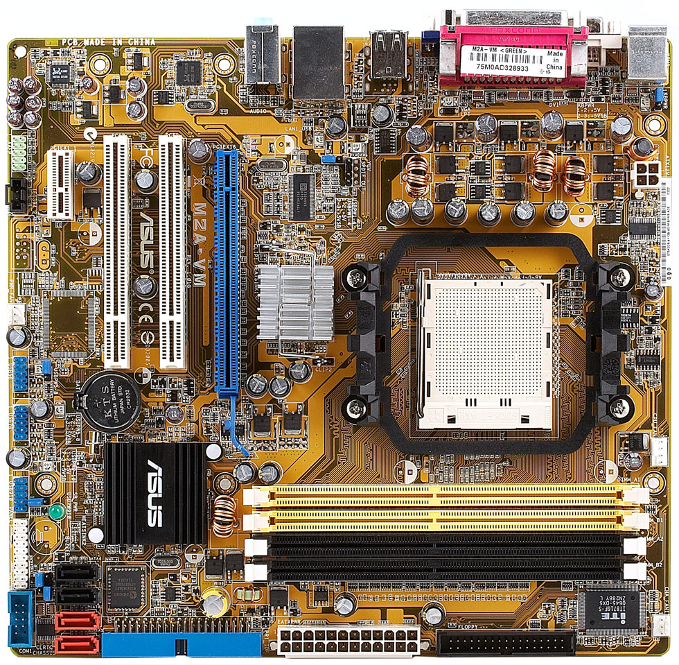
The system board's design apart from the original (actually almost standard nowadays for the inexpensive ASUS boards) "sideways" position of the IDE slot is quite traditional for microATX boards based on the given chipset. The layout is good. Despite the computer case being tight, accessing slots and jumpers is easy. In theory, we could have wished for the PCIEx1 port to be placed between the graphics and PCI slots in order to be able to install 2 PCI expansion cards after installing a graphics card. Chipset cooling, similarly to all AMD 690G series boards, is passive. However, ASUS has chosen a rather narrow and tall heat sink instead of the widely spread broad and short one recommended by AMD. It may prevent one from installing a non-standard bulky cooler onto the CPU. Although a compact cooler that fits within the dimensions of the mounting frame is more likely to be used in such a system. Cooling efficiency is standard, in similarity to the other tested system boards, even during long periods of maximum load and with no additional air flows. In an open testbed chassis with the ambient temperature of 28-30 degrees C the "system" temperature didn't exceed 45 degrees C. Chipset heat sinks have been warming up to the same temperature, which is an evidence of more than decent safety margin. The three-channel impulse supply voltage stabilizer uses 3 field transistors per channel, 6 capacitors of 1500 microfarad each and 4 capacitors of 1000 microfarad each. All capacitors are brand name, made by Matsushita and Rubycon. The only minus is the choice of "open" coils in the voltage stabilizer. In certain modes under load they may "squeak", and such high-pitch noise is audible even in computers with noisy cooling systems. The board has the necessary wiring for the FireWire controller, which can be installed with M2A-VM HDMI version that comes complete with an extra card with HDMI out-ports, composite video-out and S/PDIF Out ports. Board's form-factor is microATX (245x229 mm). It is mounted to the chassis using six screws, while the right edge up to the level of peripheral ports is left unsecured. System monitoring (ITE IT8716F-S, from BIOS Setup data)
Ports, connectors and sockets on board surface
Board's rear panel (left to right, by blocks)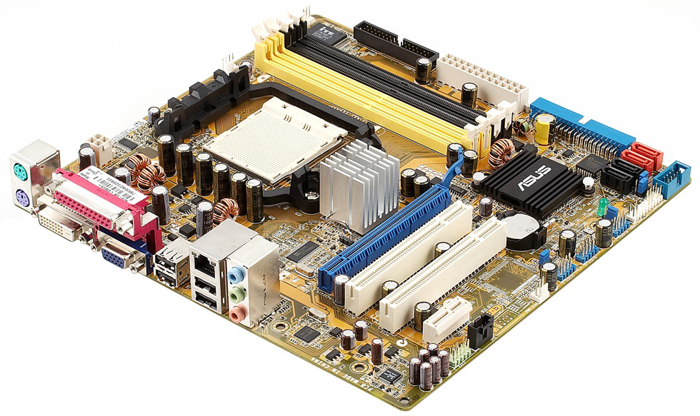 2 2
click to view the board in 3/4 perspective from the rear panel side
Package contents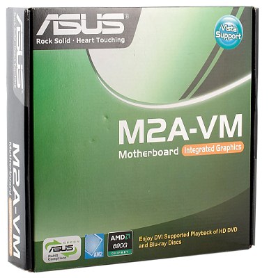
The set of brand utilities includes: ASUS Update (rewriting BIOS in Windows, with an ability to search for and download the latest version from the manufacturer's webs-site), PC Probe II (for monitoring system parameters in Windows), Music Alarm (an alarm program that uses music from a user-selected CD as alarm signal). Also included is Norton Internet Security 2006 anti-virus and firewall. Integrated controllers
We have evaluated quality of the integrated audio in 16-bit 44-KHz mode using RightMark Audio Analyzer 5.5 testing suite and ESI Juli@ sound card:
Overall rating: Very good. Such a high mark is standard for the utilized codec. Brand technologies and features
Settings
For testing we used BIOS 1001 07/16/07 version, which was the latest released at that time. The aforementioned BIOS capabilities are available in the specified version of the BIOS. Non-standard settings were not tested for operability. The choice of settings isn't rich, but it contains the necessities for successful overclocking including ability to raise the CPU and memory voltage. Unfortunately, it wasn't very helpful in practice. OverclockingIn order to evaluate the overclocking capabilities of the board and its BIOS, we overclock our testbed CPU to the highest frequency possible that also allows for stable operation. Applying this test procedure, we are able to effectively use all of the test board's supported abilities, including increasing processor core voltage, and if necessary, correcting multipliers and adjusting system and peripheral bus frequencies. However, if lowering Hyper-Transport frequency, for example, doesn't improve overclocking performance, the default multiplier is used instead. RAM is set (by using multiplier correction) to the standard frequency for the modules being used, unless the manufacturer specifies methods for improving memory overclocking, in which case their effectiveness is also explored. In order to evaluate the overclocked system's stability, we load Windows XP and run performance tests built into WinRAR (Tools menu - Benchmark and hardware test) for 10 minutes. It is important to realize that overclocking performance varies by motherboard and is, to some extent, an individual characteristic of each specific unit. For this reason, it is impossible for us, and any other review, to determine the overclocking potential of any board with megahertz precision. The practical goal of our test is to find out if the CPU's high overclocking potential is hindered by the board and to evaluate the board's behavior in non-standard BIOS modes. This test also assesses the board's ability to automatically revert to correct frequencies in the case of system hang-ups, excessive overclocking, etc.
A poor result, considering that increasing core voltage didn't improve the situation at all, neither did further decreasing of HT multiplier. Meanwhile, our CPU has been reaching 2700 MHz and more with standard voltage on boards with no settings for increasing it. Resetting frequency to the default value in case of excessive overclocking works every time, one only has to reboot the computer again. The ability to save BIOS settings in 2 profiles is also a nice feature. Apart from storing them in CMOS, it is possible to use a hard disk (SATA only), floppy disk or USB storage. PerformanceTestbed configuration:
For comparison we have chosen a Biostar TA690G-AM2 board based on the same chipset that we have tested earlier.
Once again we observe minimal performance drop in the computational tests after activation of integrated graphics core. In comparison to Biostar memory settings by ASUS have turned out to be less effective. As a result there is lagging in the most sensitive test - data compression using 7-Zip. Nevertheless, the other tests have shown almost no difference. ConclusionIn contrast to its competitors, ASUS is offering a sort of a transformer model with AMD 690G chipset. By itself M2A-VM appears to be a good foundation for a work computer, which allows connecting two displays using its own ports, and 4 displays using an outboard graphics card. The only limitation is that only a monitor with a digital-in port can be connected through the on-board DVI since no analog component (DVI-I) is provided in this particular port. For the same reason it isn't possible to use an adapter. Whereas, M2A-VM HDMI version with the help of a built-in FireWire controller and an HDVI expansion card and S/PDIF-out ports appears to be a complete solution for the HTPC. It is worth noting, that M2A-VM HDMI is the only one of all boards based on AMD 690G (and of all boards with integrated graphics in general) that allows organizing independent output of two digital video streams (via DVI and HDMI). All other boards, even those that have ports of both types on their rear panels, only allow using one at a time (of course in addition to an analog-out stream, which is available in any case). Write a comment below. No registration needed!
|
Platform · Video · Multimedia · Mobile · Other || About us & Privacy policy · Twitter · Facebook Copyright © Byrds Research & Publishing, Ltd., 1997–2011. All rights reserved. | ||||||||||||||||||||||||||||||||||||||||||||||||||||||||||||||||||||||||||||||||||||||||||||||||||||||||||||||||||||||||||||||||||||||||||||||||||


