iXBT Labs - Computer Hardware in Detail

Platform

Video

Multimedia

Mobile

Other

Mini-switch testing technique, version 1.2


Tests of mini-switches include physical tests in a real network, analyses of obtained data and subjective estimation of switch's functionality and design.

For the first part I used IOMeter utility developed by Intel. Unfortunately, the company doesn't provide its support, the program is available at its site just as is.

The IOMeter allows generating a traffic with determined parameters and gathering statistics. One can assign a lot of traffic parameters, but we were interested in generation of a traffic of the maximum intensity, that is why we chose:

  • transfer type - 100% successive
  • transfer form - 100% record
  • data block size - 64 KBytes (this is not an Ethernet packet but a data block the program works with)
  • delay time in packet transmission - minimal.

The speed results were read with the OS system utility Performance Monitor.

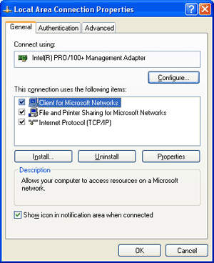
For the tests we built a peer-to-peer Fast Ethernet with 5 computers. Each had Windows XP Professional, and Intel Express 100 network adapters. We disabled the QoS (load balancing) in the network protocols, which is meant for traffic leveling and can cause speed-down in data reception/transfer.

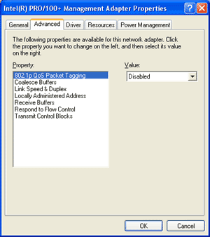
Network cards settings:

  • 802.1p QoS packet tagging (priority frame processing) - disabled.
  • Link Speed & Duplex - depends on test.

The rest settings are default.

Physical tests

  • 1. Maximum switch load.
    • 5 ports of the switch are enabled.
    • Data rate - 100Mbits, Full Duplex.
    • All to all casting mode - each host receives and transfers data from other hosts. The number of hosts (network adapters) is equal to the number of switch ports.

    Thus, we emulate communication of all computers and find out whether the switch is able to stand such load, as well as check a data rate on each port.

  • 2. Data transfer between two ports with no traffic on the others (ideal case).
    • 2.1 One-way transmission from 100Mbits Full Duplex port into 100Mbits Full Duplex one.
    • 2.2 Two-way transmission between 100Mbits Full Duplex and 100Mbits Full Duplex ports.

    The results will probably very similar between most switches because this is an ideal case and a sparing regime for the device. Nevertheless, here we define an obtainable data rate between two clients.

  • 3. Data reading from one port into the others.

  • Emulation of the situation "server and many clients".
  • 4. Data transfer between 10Mbits and 100Mbits segments. Here we examine commutation quality between two segments with different transfer rates and duplex parameters.
    • 4.1 One-way transmission from 100Mbits Full Duplex port into 10Mbits Full Duplex one.
    • 4.2 One-way transmission from 10Mbits Full Duplex port into 100Mbits Full Duplex one.
    • 4.3 Two-way transmission between 10Mbits Full Duplex and 100Mbits Full Duplex ports.
    • 4.4 One-way transmission from 100Mbits Full Duplex port into 10Mbits Half Duplex one.
    • 4.5 One-way transmission from 10Mbits Half Duplex port into 100Mbits Full Duplex one.
    • 4.6 Two-way transmission between 10Mbits Half Duplex and 100Mbits Full Duplex ports.

  • 5. 100Mbits hubs can also be connected to switch.
    • Data transfer between 100Mbits hub and client.
    • 5.1 Data transfer between 100Mbit Half Duplex port and 100Mbit Full Duplex one.
    • 5.2 One-way transmission from 100Mbits Full Duplex port into 100Mbits Half Duplex one.
    • 5.3 Two-way transmission between 100Mbits Full Duplex and 100Mbits Half Duplex ports.
    • Data transfer between 100Mbits hub and 10Mbits switch.

    • 5.4 One-way transmission from 100Mbits Half Duplex port into 10Mbits Half Duplex port.
    • 5.5 One-way transmission from 10Mbits Half Duplex port into 100Mbits Half Duplex one.
    • 5.6 Two-way transmission between 100Mbits Half Duplex and 10Mbits Half Duplex ports.
    • Data transfer between 100Mbits hub and 10Mbits client.

    • 5.7 One-way transmission from 100Mbits Half Duplex port into 10Mbits Full Duplex one.
    • 5.8 One-way transmission from 10Mbits Full Duplex port into 100Mbits Half Duplex one.
    • 5.9 Two-way transmission between 10Mbits Full Duplex and 100Mbits Half Duplex ports.

  • 6. Data transfer between two 10Mbits ports.

  • Of course, it makes no sense to connect 10Mbits network adapters to a 100Mbits port taking into account the current prices for Fast Ethernet cards, but sometimes people do it. And installation of switches in the center of a star made of hubs or combination of two 10Mbits segments happen often.
      Emulation of operation of two workstations with 10Mbits network adapters or data transfer between two 10Mbit hubs.
    • 6.1 One-way transmission from 10Mbits Full Duplex port into 10Mbits Full Duplex one.
    • 6.2 Two-way transmission between 10Mbits Full Duplex and 10Mbits Full Duplex ports.
    • Modeling of connection of two hubs to the switch's ports.

    • 6.3 One-way transmission from 10Mbits Half Duplex port into 10Mbits Half Duplex one.
    • 6.4 Two-way transmission between 10Mbits Half Duplex and 10Mbits Half Duplex ports.
    • Modeling of connection of hubs to one of the switch's ports and a 10Mbits network adapter to another.

    • 6.5 One-way transmission from 10Mbits Half Duplex port into 10Mbits Full Duplex one.
    • 6.6 One-way transmission from 10Mbits Full Duplex segment into 10Mbits Half Duplex port.
    • 6.7 Two-way transmission between 10Mbits Half Duplex and 10Mbits Full Duplex ports.

  • 7. Data transfer between 100MBit ports in the half duplex mode.

  • Emulation of operation of the switch in the mode of several joined 100MBit hubs.
    • 7.1 One-way transmission from 100Mbits Half Duplex into 100Mbits Half Duplex port.
    • 7.2 Two-way transmission between two 100Mbits Half Duplex ports.
    • 7.3 All to all casting mode in the Half Duplex 100MBit mode.

    • In the latter case 5 hosts are enabled, like in item 1. Each host receives and sends data to the others. We test ability of the switch to work in the high-speed hub commutation mode (this is one of the most popular ways to use a switch).

Analyses of obtained data

For comparison of switches we will use dimensionless integral values. Each test gets its own weighting coefficient (dimensionless positive value less than one; the sum of all weighting coefficients for each group of the tests is equal to one).
Results of each test are also converted into a dimensionless value according to the following rules:

  • The maximum theoretical speed in the current test is taken as one or 100%
  • The maximum speed for the 100MBit, Full Duplex tests is equal to 100,000,000/8/1024 = 12,207 KBytes
  • The maximum speed for the 100MBit, Half Duplex tests (two-way data transfer) is equal to 100,000,000/8/1024/2 = 6,107 KBytes
  • The maximum speed for the tests with 10MBit, Full Duplex ports is equal to 10,000,000/8/1024 = 1,221 KBytes
  • The maximum speed for the tests with 10MBit, Half Duplex ports (two-way data transfer) is equal to 10,000,000/8/1024/2 = 610 KBytes
  • The data rate of the current test is taken as X% and is calculated from the proportion.

After that the dimensionless values of the same group are summed up.

Now let's look at how the tests are divided into the groups and at their weighting coefficients:

test number weighting coefficient group
1. 0.6 Group 1 (items 1-3)
Operation in the 100MBit ports, Full Duplex
2.1 0.1
2.2 0.1
3 0.2
4.1 0.3 Group 2 (items 4.1-4.3)
Commutation between 10 and 100MBit ports, Full Duplex
4.2 0.3
4.3 0.4
4.4 0.3 Group 3 (items 4.4-4.6)
Commutation between 10Mbit Half Duplex and 100MBit Full Duplex ports
4.5 0.3
4.6 0.4
5.1 0.3 Group 4 (items 5.1-5.3)
Commutation between 100Mbit Half Duplex and 100MBit Full Duplex ports
5.2 0.3
5.3 0.4
5.4 0.3 Group 5 (items 5.4-5.6)
Commutation between 100Mbit Half Duplex and 10MBit Full Duplex ports
5.5 0.3
5.6 0.4
5.7 0.3 Group 6 (items 5.7-5.9)
Commutation between 100Mbit Half Duplex and 10MBit Half Duplex ports
5.8 0.3
5.9 0.4
6.1 0.1 Group 7 (items 6.1-6.7)
Commutation between 10Mbit ports with different duplex parameters
6.2 0.2
6.3 0.1
6.4 0.2
6.5 0.1
6.6 0.1
6.7 0.2
7.1 0.2 Group 8 (items 7.1-7.3)
Commutation between 100Mbit Half Duplex ports
7.2 0.2
7.3 0.6

Functionality and design

Functionality means, first of all, information density of a switch. As the only way for uncoltrolled switches to deliver information and statistics on their operation is through LEDs, we estimate their number and ability to reflect the maximum information of a certain port - speed of operation, full duplex, collision detection, data transfer indication, information on emergency shut-down of a port. As well as a power indicator. An uplink port is also referred to this category.

The design includes dimensions of a switch (relative to the number of its ports), a possibility to be installed both in horizontal and vertical positions, conveniently positioned indicators and a switch's appearance.

The testing technique will be further improved and extended.

Comments

Note that during the testing we came across an interesting fact - the throughput of the mini-switches with the number of ports over 5 sometimes depends on a data block size the Intel IOMeter works with (the latter is used as a traffic generator). In some cases (sometimes when a data block is 512 KBytes, and on some devices it is 32 KBytes) the switch stops sending data in 30-300 sec; to put it more precisely, data are transferred, but the speed is just bytes per second. By the way, it happens not only in the 100MBit mode on both ports, much more often such situation occurs in the 10MBit mode on one or more ports of switch. That is why it's not overfilling of the port buffers. The Performance Monitor data show that although the number of sent packets doesn't fall down (relative to a standard data rate), the number of received packets on the other side is very low (dozens times lower). Nevertheless, the meters of false or neglected packets show zeros.

Studying of the sources of the dynamo client (from the Intel IOMeter packet) showed that the program didn't touch low-level network protocols, that is why this data block can't affect a size of the tcp and arp packets. Or rather, it affects only if its size is less than 1.5 KBytes. The only explanation that I found is that traffic intensity in case of great packet sizes in the program grows up (verges towards the limit), and the switch can't cope with such load anymore. In real conditions such situation will hardly occur. But this is just my suggestion.

The question is a packet of what size should be installed into the IOMeter? 64 KBytes, we chose before, doesn't suit now for all 8-port switches. First we chose it because if the size was smaller the generated traffic didn't reach the maximum, and if it was over 64 KBytes the data rate didn't get higher considerably. Of course, it's possible to test each device at such maximum packet size when it still transfers data through itself, but in the tests of the 8-port devices we came across situations when a decrease of a packet size two or four times (relative to 64 KBytes) resulted in a growing of the data rate several times. But it happened only when at least one of the tested switch's ports worked at 10MBit.

At present, I don't have any answers to the questions, that is why the tests will be continued with 64 KBytes blocks. But since we have found out dependences of the data rates on packet sizes, there will be no conclusions like "the given device copes badly with data transfer in full duplex mode at 10MBit" because it is still unclear whether it is the device or something else is guilty.

Write a comment below. No registration needed!


Article navigation:


blog comments powered by Disqus

  Most Popular Reviews More    RSS  

AMD Phenom II X4 955, Phenom II X4 960T, Phenom II X6 1075T, and Intel Pentium G2120, Core i3-3220, Core i5-3330 Processors

Comparing old, cheap solutions from AMD with new, budget offerings from Intel.
February 1, 2013 · Processor Roundups

Inno3D GeForce GTX 670 iChill, Inno3D GeForce GTX 660 Ti Graphics Cards

A couple of mid-range adapters with original cooling systems.
January 30, 2013 · Video cards: NVIDIA GPUs

Creative Sound Blaster X-Fi Surround 5.1

An external X-Fi solution in tests.
September 9, 2008 · Sound Cards

AMD FX-8350 Processor

The first worthwhile Piledriver CPU.
September 11, 2012 · Processors: AMD

Consumed Power, Energy Consumption: Ivy Bridge vs. Sandy Bridge

Trying out the new method.
September 18, 2012 · Processors: Intel
  Latest Reviews More    RSS  

i3DSpeed, September 2013

Retested all graphics cards with the new drivers.
Oct 18, 2013 · 3Digests

i3DSpeed, August 2013

Added new benchmarks: BioShock Infinite and Metro: Last Light.
Sep 06, 2013 · 3Digests

i3DSpeed, July 2013

Added the test results of NVIDIA GeForce GTX 760 and AMD Radeon HD 7730.
Aug 05, 2013 · 3Digests

Gainward GeForce GTX 650 Ti BOOST 2GB Golden Sample Graphics Card

An excellent hybrid of GeForce GTX 650 Ti and GeForce GTX 660.
Jun 24, 2013 · Video cards: NVIDIA GPUs

i3DSpeed, May 2013

Added the test results of NVIDIA GeForce GTX 770/780.
Jun 03, 2013 · 3Digests
  Latest News More    RSS  

Platform  ·  Video  ·  Multimedia  ·  Mobile  ·  Other  ||  About us & Privacy policy  ·  Twitter  ·  Facebook


Copyright © Byrds Research & Publishing, Ltd., 1997–2011. All rights reserved.