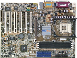
The board integrates a lot of functional elements and supports FSB 533
MHz and DDR333 memory - this is the first board on the VIA's chipsets which
officially supports these innovations. We tested the preproduction sample.
Accessories:
- Package: a box with an eagle sitting on the top of a mountain;
- Documentation: only in the PDF format;
- Cables: 1 ATA66/100/133 and 1 FDD;
- Bracket with two USB ports;
- CD with software including:
- drivers;
- utility for a smart card reader.
The production boards will also have a printed
user manual (in English), a brief installation manual (in several
languages), and a bracket for the rear computer panel because the
connectors are placed untypically.

The layout has usual drawbacks: audio-ins which are located in front
of the PCI slots, the power connectors are placed between the board's edge
with connectors for the rear computer panel and a processor's socket, and
when a video card in installed it's not easy to handle the memory modules.
It's not difficult to reach the only jumper even when the board is already
installed. Its function is shown on the textolite.
The 3-channel switching voltage regulator incorporates 10 capacitors
of 1500 uF and several less capacious.
The following controllers are integrated: an audio one based on the
chipset's capabilities and AC'97 codec VIA VT1612A with an SPDIF connector;
a network one based on the Realtek RTL8100BL; a USB 2.0 controller based
on the VIA VT6202 chip. The ITE IT8705F I/O controller provides for installation
of connectors for readers of smart cards.

Non-unsoldered connectors: a switch of an audio controller - CNR which
can be integrated on board or located on an expansion card, and a switch
for BIOS protection from writing.
The system monitoring is supported by the IT8705F from ITE. Processor
voltage (+3.3, +5 and +12 V), speed of 3 fans and temperatures of
the processor (a built-in sensor) and the board (a built-in sensor) can
be controlled. There are 3 connectors for adjustable connection of fans.
Brief characteristics of the board: memory slots - 3 DDR SDRAM;
expansion slots - AGP/ 6 PCI/ CNR; I/O ports - 2 COM/ LPT/ 2 PS/2/ 4 USB
2.0; dimensions - 305õ225 mm.

Adjustment can be carried out with:
| jumpers and switches |
Jumper to clear up the CMOS |
 |
| BIOS based on v6.00PG from Award |
Setup of memory timings |
+ |
CAS Latency, Bank Interleave, Precharge to
active, Active to precharge, Active to CMD, DRAM Burst Length,
DRAM Command Rate |
| Setup of memory frequency |
+ |
by SPD/100/133 MHz |
| Setup of AGP bus |
+ |
 |
| Setup of PCI bus |
- |
 |
| Changeable scaler of AGP and PCI buses |
- |
 |
| Manual assignment of interrupts |
- |
 |
| Changeable FSB frequency |
+ |
100-165 MHz in 1MHz steps |
| Changeable CPU multiplier |
+ |
x8-x50 |
| Changeable core voltage |
+ |
1.1-1.85 V in 0.025V steps |
| Changeable memory voltage |
+ |
2.5, 2.6, 2.7 and 2.8 V |
| Changeable chipset voltage |
- |
 |
| Changeable AGP bus voltage |
- |
 |
We used the latest available version of the BIOS - 2.21.
The board is rich in functional components and can be an excellent base
for a powerful computer with all models of the Intel Pentium 4 processor.
Test results:
Write a comment below. No registration needed!


