 |
||
|
||
| ||
|
||
|
||
| ||
By Peter Popov
Well, it's quite a problem to determine a genre of this work. Formally, I'm going to review the current state of affairs in the computer graphics. By Aristotle this work has:
A bit of historyTen years ago, in 1992, SGI (Silicon Graphics) unveiled the OpenGL 1.0 specification. This program interface was mostly based on the proprietary IRIS GL library supported since 1982. For development of the new interface they established the OpenGL Architecture Review Board {ARB}. That is why this year we can celebrate the tenth anniversary of "the standard graphics interface with an open face" and the twentieth one of the interfaces of the real-time computer graphics from SGI. First of all, let's speak about a standard pipeline from Silicon Graphics. A classical 3D graphics library is, in fact, a black box with one tray to supply triangles, a lot of switches and adjustment knobs. What happens to a triangle inside the box? [Apart from a triangle there are such primitives as points, line segments and convex polygons of not only three vertices. But we will trace only triangles]. A coordinate and a normal of each triangle's vertex are converted with the model matrix {MODELVIEW}. [The OpenGL has several matrix stacks. A very handy approach.] Generation of a color characteristic, which takes place when the lighting calculation is enabled, is based on geometrical properties of vertices, properties of materials and positions of light sources (if a color is specified its value is just rewritten). If generation of texture coordinates is also enabled they change and then get transformed with the texture matrix. This is a geometrical stage. After that a 3D PROJECTION matrix is applied to each vertex. The obtained 4 projection coordinates {x,y,z,w} get normalized: {x/w,y/w,z/w,1}. Such conversion makes a unit cube of a viewing pyramid. A part of a triangle which doesn't get into the viewing pyramid {frustum} is clipped. It means that only a part of a triangle which is seen in the window is drawn; this part must be closer to the viewer than the far clipping place and farther than the close one. Client clip planes are also applied to a triangle. The first two components of three normalized coordinates are used to position a projection of a triangle in the window. The third component is used afterwards for the Z test {Z test~depth test}. A triangle projected onto the plane can get a clockwise orientation or a counter-clockwise one. If you set the "right" orientation, only such triangles will be drawn {face cull}. The next stage is rasterization. All attributes get interpolated onto pixels which belong to the triangle given the projective correction. Texture coordinates are calculated for all texture stages; values selected from the textures get mixed successively forming one color value. A stencil value and a Z one are also calculated for the given pixel. These three values form a fragment. For a fragment there are several tests {depth, alpha, stencil}. If the tests are successful a new color mixes with the old one with the help of the current blend mode, and stencil and Z values are updated. The whole virtual OpenGL machine is controlled by a set of Boolean variables which include a certain pipeline branch (lighting calculation, texture coordinates, pixel tests and so on) and numerical values related with the given current stage. This is a standard graphics pipeline. [ Only in the polygon processing part. The OpenGL has high-level spline primitives and integrated means of image processing - pixel arrays.] Standard pipeline and geometryObjects in 3D graphics are made of triangles. Triangle's vertices have geometrical, color and texture characteristics defined. Usually triangles have common vertices, and it's not rational to duplicate information. A standard description method consists in determination of two arrays - a Vertex Buffer {VB} which stores geometrical, color and texture characteristics of vertices, and an Index Buffer {IB} where three successive indices form a separate triangle. Index arrays can be structured not only as a set of separate triangles, but also as a strip or a fan of triangles.
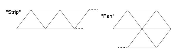 These are more economical geometry indexing ways. A handy, at first sight, approach turns to be a nightmare in a real life. For an arbitrary polygonal model the V/T ratio (vertices/triangles) is equal approximately to 0.5 - for two triangles there is one new vertex. You can make sure using the Eiler formula. The set of triangles has it equal to 3.0, for strips and fans of triangles this ratio tends to 1 (remaining beyond) as the length grows. It's quite complicated to divide an arbitrary model specified as a set of triangles into strips and fans. The algorithms are awful and slow. Short strips are joined by such a terrible method as an insertion of fake triangles. But anyway, the V/T ratio remains twice worse than the optimal one. Note that a rate of geometrical transformation of modern chips is often a bottleneck. One more side of the geometry organization problem is hardware architecture. And a V/T reduction method which is called caching of processed vertices. For every index there is a unique vertex. Processed vertices are put into the LILO queue. And if a processed copy of a certain vertex already exists in the queue, which is looked for according to its index, the vertex isn't processed anymore. Such geometry organization reduces the V/T ratio. In case of a very long queue (100 - 1000 vertices) and if triangles are put in good order the ratio comes close to optimal 0.5, that is why I'd like this order to be confirmed. That is, a quite long buffer of processed vertices, at least 256 elements, must be specified as a necessary ingredient of a right video accelerator. No strips, no fans, just triangles. A static index buffer can look like this: BeginStaticTriangleBuffer(TriangleBufferHandle);
Every three Read* commands form one triangle. You might disagree that it's good to use cache memory in the interface. But if chips are structured so that an optimal programming allows for a considerable rate growth such structure must be accounted for. It's quite a problem to optimize an application for chips whose internal structure is little known, especially considering that a cache size in modern chips differs as much as several times. The optimization for a modern video accelerator is like looking for a dark cat in a dark room. The problem is of the geometrical character - the triangles have common vertices. The cache should be considered as a good way to indicate local rules of attaching geometry. It's like generalization of strips and fans. A strip is, in fact, an implicit caching method (two vertices of the last triangle remain). I'd agree if they remove strips and fans from the interface and provide rendering of a set of triangles with caching being indicated explicitly. [Note that a static index buffer resulted from such procedure can be easily compressed as the most part of operations with indices are carried out in the cache, and these indices are not large numbers.] The first method is used for the static geometry. And there is an old method of rendering of a set of triangles without explicit indication of a caching sequence but with its utilization. It could be enough if hardware manufacturers followed recommendations to make a hardware cache of the specified type (LILO or LRU) and length. Now let's speak about procedure surfaces and tessellation. With standard splines (and rational functions) it's quite difficult to achieve a normal continuity (in fact, I don't know any working algorithms of attachment of spline curves on nonuniform meshes). There is another approach. Its first part is that for a triangle (or a quadrangle) a tessellation level is specified for each edge. The library tessellates a patch (only topological, without geometrical information) according to the edge tessellation. It's convenient to make a tessellation floating (like in the OpenGL extension of gl_nv_evaluators). There new vertices "are born" in the center of the edges:  Now the key question is generation of coordinates (and other attributes) for vertices. How can it be done? Maybe, using textures. Let's consider a uniform mesh (from a topological standpoint) whose notes contain attributes - a normal, a coordinate, a color etc. A set of textures. [ It's interesting that triangular textures are unusual in graphics, while their quadrangular brothers are rather popular. Nevertheless, filtering operations can be even simpler. Here it's better to use as a coordinate u,v,w values with the correlation of u+v+w=1. Such textures are better to use for separate triangles, say, for lighting maps. It this case it's easier to attach them.] The theoretically obtained vertices of a tessellated patch have u,v texture coordinates for quadrangular patches and three barycentric coordinates u,v,w:u+v+w=1 in the triangular case. The library samples a texture to the given address for each vertex. A standard bilinear interpolation is not that bad, but in this case it makes no sense to use a larger tessellation than a texture resolution. A spline interpolation on each texel suits better (say, an analog of pn_triangles aka TrueForm). Now let's turn to a method of delivering of vertex arrays. At present, it's standard to represent each vector component (coordinate, normal, texture coordinates) as ANSI 32bit float. But quite often such precision is unnecessary, 16 bits per component are enough for a normal. A lot of objects are well localized (e.g., monster models), and 16 bits per components are also enough for a coordinate. And as far as texture coordinates are concerned, we can also reduce precision without noticeable quality loss. That is why it is rational to have a support of compressed formats for vertex attributes. Such possibility existed in the classical OpenGL interface as well, but there a user could choose a format himself, and he couldn't hope for the decoding being fast. But it was a loop - programmers were not sure the low-precision format was supported, and vendors didn't support such formats as though they were not in demand. I think that the right method is delivery of static arrays in the uniform format (float) and their compression in the API, with the API giving a list of available formats itself. It's like usage of compressed textures. The ordinary approach is that an uncompressed copy of a texture is loaded into the RAM. The API compresses it and records into the video memory. The original copy is deleted. Does it makes sense to use compression? It doesn't if a double gain in the required memory volume doesn't seem decent. Question: How are the geometry problems solved in the OpenGL 2.0? Answer: in no way. Arrays are objects. It's possible to access them directly, you can't use any compression or optimization of indices or caching. Compressed formats are allowed - it's possible to use bytes and short words {GL_SHORT, 16 bit}. But we are not sure again that such formats will be processed quickly. Tessellation is not included into the interface just because "Nobody knows what it is". They added separate index arrays for different vertex attributes. It supposedly helps programmers to solve collisions when vertices share some attributes (for example, coordinates) and don't share others (for example, color). A base example is a cube with faces of different colors. This is an arguable benefit. Determination of visibility on a standard pipelineFor a standard determination of visibility (or, rather, invisibility) there is an hierarchical subdivision of a screen plane. If geometrical objects are ordered according to the distance from a viewer (from the closest to the farthest) we then can speak about a potential invisibility of an object. Today vendors support this visibility determination in the 3D API. HP_occlusion_test extension is used for it. The OpenGL 2.0 draft doesn't mention any visibility determination at all. I offer the following strategy of a portal rendering support. We enter a new object - CSG polygon stack. Each element of the stack is a set of scanlines which limit a certain area on the screen. In particular, this is a mask for rendering. It's possible to place polygon P into the stack by crossing the area, limited by a current element on the stack's vertex, and P's projection. A user can get information that the upper element of the stack is empty and then step back. So, with such a stack of polygons we can determine visibility of separate parts of the scene with the help of portal algorithms, thus, combining a rendering process and a visibility determination. The algorithm could work extremely well in scenes similar to shooter's levels as it could provide a zero overdraw factor. In this algorithm polygons can be used several times, and it would be nice to have a small cache to place there transformed triangles. Standard pipeline, translucency and 3D effectsWe can discern the situations when semitransparent object A is in front of object B and vice versa. It means that a programmer must sort semitransparent triangles from the closest to the farthest one relative to a viewer and draw them in this particular order. But it's strange that a programmer must do it because transformation of vertex coordinates is done on a hardware level. The problem is aggravated by overlapping triangles when we can't know which one is closer. Sorting of triangles is not an appropriate solution. The sorting must be done on a pixel level. I know about a quite good algorithm which can be called "per-pixel sorting with a Z buffer". Just as we can find the closest non-transparent pixel with the Z buffer, we can find the farthest semitransparent one, then that which comes in front of it and so on. The algorithm written in a pseudocode looks as this: Variables: Zmin, Zminmax For all polygons' pixels located above the given
pixel: Use Z minmax as Zmin for the next cycle. Such process can be carried out on modern equipment. But this realization is not effective. Note that for this process we must collect all semitransparent triangles. A step of the algorithm consists in rendering of all these triangles. One more Z buffer is used additionally. If the number of overlapping equals N, we must run the algorithm N times. We can speed up the process if at each step we take out of the list those semitransprent triangles whose all pixels have taken the required places. The overall number of cycles reduces approximately twice. There are some optimizations which allow drawing semitransparent objects correctly. There are such optimizations which are carried out by an API and by a programmer. Can this feature be realized in the OpenGL 2.0? It can be done with pixel shaders, but it's not effective enough. Because there is no any reverse data flow from the rasterization stage. Now a little on 3D visibility. I really want that a 3D texture be considered as an array of voxels. I want to add 3D primitives to standard ones, for example, a tetrahedron. Each vertex has respective coordinates in a 3D texture. The rendering method is ray tracing from a value in the Z buffer to a viewer through an object. However, there are problems of rendering of overlapping objects. 3D graphics objects. SynchronizationWhat are objects of 3D graphics? The developers of the OpenGL 2.0 consider the following objects:
All OpenGL 2.0 objects are stored in the API. When an objects is created it's necessary to specify its priority and policy. Such approach is aimed at ordering a data flow by putting the most important information into the fastest memory. They also solve a problem of synchronization of OpenGL calls at the expense of asynchronous instructions and ways to define completion of the given instruction. Such innovations seem to be quite useful, but they also seem very obvious. Vertex shaders are copied from DX's VB and IB, that is why there is nothing to discuss; the display lists remained from the old times. Shader objects correspond to vertex and pixel shaders. Though it would be better to call the latter Fragment Shaders. Shaders of both types together are called a Program Object. As far as storing of pixel structures is concerned the developers has a rich imagination... All those Textures, Images, Buffers and Display Buffers can stump even advanced users. Somehow or other, all functionality in this sphere can be described simply. There is a configurable buffer which is a render target. There is one predefined buffer of this kind - a display buffer. A user can also create several off-screen render buffers. Such render buffers are like a folder with several sheets-surfaces such as a color buffer, Z buffer, stencil buffer, aux data buffer, accumulation buffer etc. Almost any separate surface can be deleted from the render buffer and attached to an arbitrary texture; it's called rendering to texture. That is why textures and rendering buffers are objects which contain one or several links to pixel data. But can several active rendering buffers exist simultaneously? It could be quite useful as it's often needed to render the same data into a texture(s) and a display buffer. The current API version doesn't indicate it. It would also be handy if we could configure 6 simultaneously active rendering buffers so that a triangle can be rendered into a cube texture not 6 times but only once. Dreams... I can't neglect aux data buffers. Such buffer contains up to 4 figures like float per pixel. It's claimed that such buffers can be useful for realization of multipass rendering algorithms. Maybe it's true, but there are algorithms like multilayer stencil buffer where such high precision is unnecessary. Sometimes several bytes are better than one float. Of course, such buffer is an extension of accumulation buffers, which, nevertheless, are included in the interface drafts, though functionality of aux data buffers is much wider at the expense of read/write access in the shader. It's possible to organize the second stencil buffer or an auxilary Z buffer for correct rendering of semitransparent polygons. In realization of a multipass rendering one can save values calculated beforehand pixel by pixel. The documentation also mentions F LILO buffers meant for storage of processed fragments. The developers of the OpenGL 2.0 didn't represent them in the current documentation though they wanted much. Well, it is a stylish feature though a bit useless. Now let's address to stream processing of pixel arrays. The OpenGL 2.0 provides the most powerful instruments for reading of client data and their conversion into the internal format (pack-unpack shaders). But I'm not interested in it. What interests me is filters which were taken off from the OpenGL specification. Filters which blur depending on Z buffer values or its linearity degree are very useful for realization of a camera's focus or for quality blurring of shadows obtained with the stencil buffer. Funny things happen to convolution filters. A possibility to apply a filter to an image is provided in the OpenGL 1.2 standard, but there are not many hardware manufacturers who support it. There is a tendency to realize convolution filters by multiple sampling of one texture. It mustn't be allowable. A cost of convolution of a 4x4 filter with image's pixels is incomparable with the cost of 16 texture's samplings, especially considering that convolution operations are of the stream type with a predictable memory access and a good optimization possibility on the lowest level. What about the OpenGL 2.0? The documentation advocates realization of filters by multiple reading from a texture in a pixel shader. I don't like this approach. One of the best solutions is indication of an explicitly specified filter as a texture interpolation method. I will discuss this approach later, in the shader part. The current documentation seems to be raw as far as storing and usage of pixel data are concerned. Again about geometryThe ideal static geometry [in terms of topology and, possibly, constancy of vertex attributes. However, such geometry can deliver different images, for example, when using a matrix skinning and animation of a palette of matrices] should be in the form of vertex buffer {VB} and a buffer of separate triangles with explicit specification of the caching method. The polygonal graphics has at least two well-known algorithms which account for topology of a model in that degree which poorly works with the VB+TB. The first algorithm is calculation of normals by triangle averaging. First of all, a coordinate is calculated for all vertices in the model space. After that a normal is calculated for each triangle. For each vertex a normal is a result of averaging of normals of triangles which have the given vertex. Apart from normals it's possible to calculate the same way a local coordinate system which is a very important object in the per-pixel lighting. In case of matrix skinning a normal is usually calculated by the weighted operation of the matrices by which a coordinate is transformed. It often gives a wrong result. It turned out that averaging of a normal is the only appropriate way to calculate it. In case of shader variants of deformable geometry it's necessary to make a lot of entries into the memory. Thus, this simple algorithm turns out to be very slow. So, locality of geometry with the caching method specified explicitly provides a good realization of this method. The second algorithm is calculation of shade volumes for shadows made with the stencil buffer. This algorithms uses a weaker topological information and can be accelerated on a hardware level. Here we must have a small cache of processed triangles or their edges. It seems to me that these two methods are desirable ingredients of a good API of the polygonal graphics, as well as geometrical operations are, like subdivision surfaces. In the OpenGL 2.0 it's impossible to realize similar functionality. There are no non-trivial ways to process geometry with non-shader procedures. In general, the standard pipeline remains, and only two stages - vertex processing (we called it a geometrical stage) and fragment rasterization (but not conventional tests and color mixing) are realized with the help of the programmable shader language. Pixel and vertex effectsNow we are going to talk about a shader language of the OpenGL 2.0. Vertex shader: const ubyte *phongVertex = " Pixel shader: const ubyte *phongFragment = " Note that the language is based on C. Input data of the vertex shader are predefined variables gl_Vertex, gl_Normal. These data are defined for each vertex. The result of operation of the vertex shader is stored in the "varying vec3 normal". "Varying" means that the given variable will be interpolated on a triangle surface. This variable, together with static data diffuseIntensity, specularIntensity etc. becomes available in the pixel shader. That is, pixel and vertex shaders need to be linked. Data types allowable in the shaders of both types are float numbers, vectors of real numbers which are 2,3,4 long; 2 x 2, 3 x 3, 4 x 4 matrices and int type numbers. Structures and arrays of such data are also allowable. The vector language is quite convenient at the expense of *,+ operators and masking: vec4 dup = pos.xxyy; Data can be constants defined at the compilation stage, Read Only constants set via the API calls, local shader's variables, and varying variables which link together vertex and pixel shaders. There are directives of a preprocessor, {if-else, for, do-while} constructions and subroutine call procedures. The integrated functions include trigonometrical, geometrical, {max-min-fract-clamp etc.} functions, matrix multiplication, noise function. Pixel shaders support texture sampling (with explicit specifying of a detailing level), for variables there are partial derivatives in window coordinates. I wish the pixel shader language had filters (as a way of texture sampling). Coefficients of such filter can be determined either statically or dynamically. A good example of a dynamic filter is a Guassian filter with a blur radius defined for each pixel. Or an anisotropic filter which is specified as an ellipse in the texture space. The following nearest-convolution filter can be a typical application of explicit texture filter-interpolation. U-V coordinates are transformed to the nearest texel in the texture space, a matrix of values which surround a given texel is chosen and convoluted with the static filter. It's much better than: tex = TexCoord0; Unfortunately, vertex shaders do not include texture sampling operations. It's better to represent many functions not in an analytical form but as an array of values. Besides, shaders do not provide for an operation of free address reading of vertex arrays from OpenGL. And it's impossible to write into the memory in shaders. The shader representation looks quite poor, though it becomes better in new versions. For example, there is an operator of array indexing []. In such form of recording for an array it's possible to create an index file in the integer form. But there is also an element function (a, float i) the call of which is equivalent to a[(int)i]. When I asked the support service why I couldn't write a[(int)i] they said the language didn't allow for the type cast. But now you can cast "float" to "int", though the element function remains. An important improvement concerns buffer reading. Earlier there was the lookup function for this purpose. Now they use the right way to access old values of color, Z buffer and stencil buffer, by reading from RO variables: vec4 gl_FBColor; Strangely enough, the OpenGL developers are deeply attached to classical tests and blend operations. For example, a classical blend function like GL_ONE,GL_ONE looks like this: gl_FragColor=gl_FBColor+calculated_color; It's claimed that realization with the shader's help will be slower than the standard one because of the extremely deep pipelining and new additional dependences. I don't think so. The only test which should be left unprogrammable is a Z test. Because modern chips build hierarchical structures of data for Z. Why don't they establish such restrictions in the language which would allow using effectively hierarchical structures for a preliminary tile test? The hierarchy is not bad for other data types as well, for example, for a stencil buffer. Note that in this part I don't start description of the OpenGL 2.0 with the results of my meditation of this subject. It's simple. Why to invent a language which is so similar to a higher-level language and which is not such? Having extended the rules it's possible to get a language compiled in the API and which replaces C completely. Namely, we can enter an operation of triangle rendering. Procedures of such language are not called in case of vertex processing. A user calls such procedures directly (through the API call) transferring OpenGL arrays as a parameter of a number. Usually in this procedure vertices are transformed in a cycle by the shader subroutine forming separate triangles delivered to the rasterization stage. It's only needed to add a triangle rasterization instruction with three specified vertices and their varying characteristics. Such language can contain integrated functions, for example, for patch tessellation. Integrated caches would be a good solution also. [like LRU_map<GenType, int> Cache. Functionality is that the cache stores a fixed number, e.g. 256, of object-key pairs which are last to be written in. You can delete objects according to a key, define whether an object with the given key exists, write an object-key pair.] If we want to retail a possibility of parallel implementation of shader procedures we can bring in an operation of a stream array processing with a function which can modify only a current element of the array and doesn't use other elements. Anyway, the entire functionality of a pipeline is realized in the program code in a special language. Low-level and higher-level approachesWe have ascertained that by an insignificant extension of the shader syntax it's possible to create a language which would meet all thinkable requirements of programmers of 3D graphics. The fact that a programmer has everything in his hands is a simultaneously weak and strong side of such approach. The language will be better (better than C at the expense of support of vector types), but every smallest detail must be realized manually. The second graphics development way is a completely higher-level approach, description of a scene as a whole. In this case, a scene is described as a set of geometrical objects and effects on them. Each object is localized in the space, i.e. the API knows a volume (sphere, cube, pyramid etc.) which confines a certain object. Effects (a positioned light source, a fog area etc.) are also localized in the space, each effect has a specified code (here the shader language looks very convenient ) which modifies vertex characteristics and a code which works on a pixel level. For effects a sequence of their application is specified. A 3D graphics library must define itself a set of effects for each object and compile the net effect. Before being rendered, a scene is entirely described, the library determines visibility, sorts objects according to the distance from a viewer and controls rendering of semitransparent objects. What approach is more promising? The higher-level one could be better if there were no objective problems with visibility determination for arbitrary scenes. The low-level approach seems to be quite complicated for realization both on the driver writing level and on the programming one. The same problems with visibility determination remain. ConclusionHow can we characterize OpenGL 2.0 presentations in general? Item 0. Establishment of objects as essentials of 3D graphics. The idea of polices and priorities. A natural step.
However, there are some sound improvements as compared with the last-year
version. And I can see already a silhouette of a convenient and reliable
interface.
Write a comment below. No registration needed!
|
Platform · Video · Multimedia · Mobile · Other || About us & Privacy policy · Twitter · Facebook Copyright © Byrds Research & Publishing, Ltd., 1997–2011. All rights reserved. |


