 |
||
|
||
| ||
|
||
|
||
| ||
Note: the author does not take any responsibility for partial or complete out-of-order operation of a mouse and/or a computer and/or other devices caused directly or indirectly by implementation of instructions described in this article. If you have decided to follow the given algorithm, then be careful. To disassemble a mouse priced at around $50? Theoretically such mice must never break... but the reality is much worse than theory, and a warranty period usually ends by the time of a damage. There is only one way out - to disassemble it carefully, screw by screw. My mouse didn't break itself, it was me who poured some bear which got inside the mouse (and in this case it is necessary to clean it completely). Many users also complain that a cable often bends and breaks right near the mouse's base to make the latter to perform badly. So, let's start. Don't forget to disconnect your mouse from the computer! 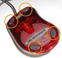 First of all, it is necessary to find fastening screws. As usual, they are located under stickers that simplify sliding; they can be found on the below surface of the device. You should carefully hock the stickers with a knife thus separating them from the mouse (you shouldn't break them, that is why you have to keep a knife's surface parallel to the sticker's surface), and put them aside with a sticky side up: Now you can see 4 screws that you must take out carefully. Now comes the most interesting - a lid removal. Apart from the screws, the lid is mounted with a small clamp located inside the mouse (look at the photo): 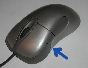 To remove the lid you must separate its right part from the base (it is made of red semitransparent plastic), and then draw the lid up to the left (if you are looking at the mouse from the behind). What you have done is enough to repair a broken cable. Now you should carefully produce the cable out of a notch and, having cut 5-7 cm, solder it back to the connector. But the whole process of a mouse disassembly hasn't yet been completed, and we can continue our work for a deeper examination and repair. Now we have to take out a scroller, for what we are taking the wheel and carefully dragging it up, thus releasing the right part from the joint. Then you are to shift it to the right and remove from the mount. Here is what we have come it: 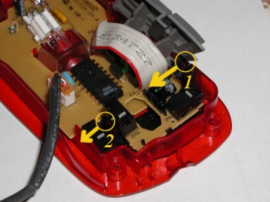 For removing a wheel mounting block you must implement the following steps. First you must pull aside a support according to the arrow, and lift this side of the block to prevent clamping (step 1 on the figure). Then you must pull the clamp (2) with a screwdriver in the same direction and completely separate the block from the mouse. It contains the mounting schematic of the scroller. This schematic is easy to remove by pulling away lugs, on which an axle is mounted, and by pushing out the card. So, you get the card released. 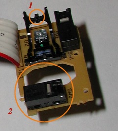 Now we should adjust the tactile response during the scroller rotation. The discrete rotation of the scroller is accounted for by a ribbed cylindrical surface on its spindle, and by a small jut on a spring frame (# 1 on the figure). To feel better each step of the scroller rotation, you should make this jut a bit higher. To implement it you may incandesce a knife to make a jut of a desired form and size. For a more gradual rotation you should make this jut a bit lower. Besides, you can eliminate a vertical backlash when pressing the wheel. You should take a soldering iron and, having heated the contacts of a micro-switch (2 on the figure), lift it a little bit. The axle of the wheel will be supported by the micro-switch, thus providing no room for a backlash. But if you lift a micro-switch too much, the wheel will rotate with great difficulty. Therefore, you must feel how the wheel rotates before the final assemblage. Now, if you didn't pour some liquid inside, you can start assembling your mouse. Otherwise, you should follow us till the end. Now we are to remove side buttons: 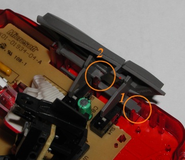 It is better to start with a smaller one. By careful raising it up, you should release one side of the axle from the joint (on the figure - 1) and, by pulling forward, take out the button. The large button is to be released the same way: by pulling it up, release one side (2), and, by slight pulling the newly released support forward, pull the button up forward, thus releasing it completely from the mouse. Now it is time to take out the main printed circuit card. It is mounted with three clamps. First of all, pull back the first one (which is located near the front edge) and then take out the remained ones (they are located behind the backlight unit; circled on the figure): 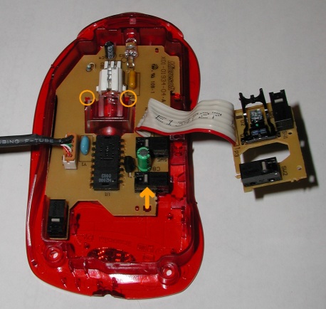 Now you should carefully take out the card from the case, hocking its front edge. Now look at the card: 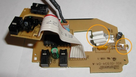 LEDs of the working backlight and of the decorative one are circled on the photo. The base of the mouse with a focusing system is also of great interest: 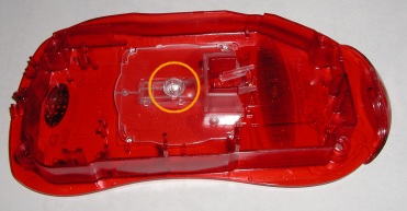 Here you can see a focusing lens of the light reflected from the mount. A focused beam of light gets onto a photo receiver, mounted with the DSP in one unit (which controls the operation of an optical sensor). The lens is implemented on a glass plate. The latter is pressed to the base with the printed circuit board, and now can be easily removed to get a shower :) Now you can wash the components. It should be noted that no abradants or dissolvents can be used for this purpose. The best way is to wash it under running water and dry them well afterwards. The assemblage is to be implemented in the reverse order. I must only warn you that the clamp of the lid won't take the right position immediately. That is why, just press the lid carefully. If all operations are implemented carefully, the mouse must work at
once. But if it refuses to perform its duties, then remove the lid again
and check the contact since it often causes bad operation of mice.
Write a comment below. No registration needed!
|
Platform · Video · Multimedia · Mobile · Other || About us & Privacy policy · Twitter · Facebook Copyright © Byrds Research & Publishing, Ltd., 1997–2011. All rights reserved. |


