 |
||
|
||
| ||
|
||
|
||
| ||
Quite often when purchasing a new product you consult various Internet sites in order to find a model best suited for you. Some of such publications turn to be quite interesting and informative. But I should note that the vast majority of my colleges take testing of coolers not seriously. And as a result, publishing data of incorrectly carried out experiments mislead not only themselves, but also their readers. Having a great deal of theoretical and practical data at our disposal we have developed our own strategy of testing coolers which allows for a quite objective estimation of their performance. Initial prerequisitesThere is a quantitative characteristic of heat-exchanging processes between a surface of some body and environment called a heat-transfer factor a (W/m2K). A heat-transfer factor is a constant of proportionality in the Newton's heat transfer law: q = aDT, q - density of a heat flaw (W/m2), and DT - temperature difference between a body's surface and the environment. A heat transfer factor describes the intensity of heat exchange: at low values (hindered heat exchange) a temperature of the body's surface is much higher than that of the environment, at high values (intensive heat exchange) a temperature of the surface doesn't differ much from that of the environment. It should be noted that a heat-transfer factor is not a physical characteristic of a body, but it is defined by its structural parameters and environment parameters. In the engineering practice usage of a heat-transfer factor is not always justified, that is why they often use its reciprocal called thermal resistance q (m2K/W). Here we mean external thermal resistance that describes heat exchange processes in a so called boundary layer. For describing heat exchange processes inside a body we use an internal thermal resistance that is defined by structural parameters of a body and heat conductivity of the material. The sum of these two characteristics makes a total thermal resistance (let's call it just thermal resistance), it is one of the major characteristics of any heat-exchanging system. Many manufacturers specify thermal resistnace as one of the major technical characteristics of their products (sometimes it is measured in °C/W). It may seem that now it is easy to calculate temperature. But in fact it is not so simple. First of all, there is no a universal approach for experimental estimation of thermal resistance. Some manufacturers give a thermal resistance of a "pure" cooler (qca - theta case to ambient), which defines a temperature of the die's surface. Some specify a thermal resistance of a system processor-cooler (qja - theta junction to ambient), which defines a temperature of the core. Besides, it is difficult to get the information from a manufacturer on what thermal resistance is given. Secondly, some manufacturers specify just calculated values of thermal resistance which are twice or three times lower than the real ones! Third, due to some physical effects (spread resistance effect is the most considerable), which can take place when a surface of a heat source (a die) is much lower than a surface of a heat sink base, a real thermal resistance of a cooler increases at least by a factor of 1.5. Configurations of test simulators used by some manufacturers don't allow for it. As a result, there is too little that we can get from characteristics given by manufacturers, that is why we set upon our own examination of performance of coolers. First of all, we have to receive questions for the following answers:
Selecting a test systemIt is clear that a temperature must be a primary result of our testing. But what temperature? In the engineering practice cooling systems of microelectronic devices are described through one of these parameters (or through both): thermal resistance qca or qja. Note that both parameters are sums of other minor thermal resistances, but let's leave this fact for a while. Knowing ambient temperature and the dissipated power for the first parameter we must find a temperature of the surface of the device cooled, and for the second parameter it is necessary to find some internal temperature of the device. In our case, there are a temperature of the die's surface and a temperature of the core. Now lets see how to measure them. There are two ways of building a test platform. The first is to simulate heat load of the processor with a heating element (a test simulator). The second way is to use the processor itself (a computer stand). The first way is preferred only by a few advanced cooler manufacturers and research labs. A test simulator consists of a prototype of a mainboard with a heating element mounted into a socket (transistors, film element etc.), a set of hot plates and measuring equipment. 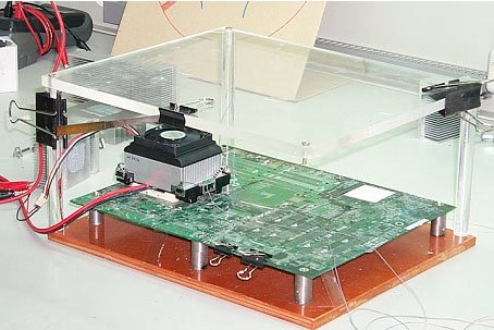 The illustration is given by Asia Vital Components Co. An advantage of this method is high accuracy and correctness of the results obtained. By varying heat load and configuration of hot plates one can define accurate values of thermal resistances. Unfortunately, a technically primitive but quite correct simulator costs several thousands of dollars. And with high-accuracy measuring equipment its cost grows ten times. The second method gives more freedom in choosing and costs much less. There is an Intel's platform, there is an AMD's platform, and at last there are various digital thermometers, if possibilities of temperature monitoring of mainboards are not satisfactory. But despite so wide range, the right choice is only one. Some sites use digital thermometers with a thermocouple of T-shape or K-shape as a temperature sensor (the Omega HH23 thermometer is one of the most popular). The guys say that measurements are high-accuracy. Is it true? 1. A temperature characteristic of a thermocouple (dependance of a contact thermal emf on the temperature difference between contacts) is nonlinear. In widely available digital thermometers a system of linearization of this characteristic is absent. That is why it doesn't make sense to speak about correct comparison analyses of the temperatures. 2. For measuring an absolute temperature with a thermocouple we need the temperature standard. Circuits of hardware compensation of the standard contact are used in digital thermometers. In cheap thermometers such circuits are realized quite poorly. 3. Thermocouples need adjustment. Those included in a standard complete set of thermometers are not adjusted. In this case we need portable calibrators, which for high-accuracy adjustment are very expensive, they use natural temperature standards. But there is one more negative factor: even if a thermocouple is well-adjusted there are a lot of negative factors that affect it with time (high moisture, corrosion, mechanical micro damages of a junction etc.), so it needs readjustment. 4. For temperature measurements with a thermocouple it is necessary to make mini-gutters or reach-through holes in the heat sink base. But they distort natural temperature field in the system processor-cooler, and the results become untrue. 5. It is impossible to provide a contact between a thermocouple and a heat sink without heat losses. Additional contact thermal resistance will inevitably appear, which will lead to wrong results, especially when a thermocouple is installed in reach-through holes in the heat sink base. Although it is not a complete list of problems when using a thermocouple, they are enough to leave a thermocouple aside. Now let's speak about an AMD's platform. One can often come across temperature tests based on the readings of a thermistor sensor mounted in the mainboard's socket. Such tests have no right to exist. Usage of external thermistor sensors instead of a thermocouple don't save the situation. Why everything is so bad? 1. A temperature characteristic of a thermistor (dependance of a thermistor resistance on temperature) is too non-linear. And results become more distorted with increase in temperature. 2. Like in case of a thermocouple (when mounting a thermistor into a "crippled" heat sink) contact thermal resistance is inevitably to appear. This again gives wrong results. 3. When a thermistor is mounted in a socket, the results obtained have nearly nothing to do with a core temperature or even with a die's surface temperature. The results reflect the character of the secondary heat flow (core - lower part of a processor's case - socket) and gives no idea about the primary heat flow (core - die surface - cooler). When a thermistor doesn't even touch a processor case is an especially bad case. Well, let's see what an Intel's platform can offer. Starting from Pentium II and Celeron, Intel has been equipping its processors with a thermal diode designed for core temperature measurements (but this in fact is a transistor in diode implementation located near an I/O unit of the processor). The rumor has it that the results obtained with such diode are not accurate. Is it true? No, it's not! Temperature measurements with a thermal diode are differential. A ratio that connects the differences between voltages on the junction at a fast transition of the diode from a circuit with current N*I into a circuit with current I is used in practice DV = (nkT/q)*ln N, DV - difference of voltages, n - non-ideality factor, k - Boltzmann constant, q - electron charge. Since n, k, q, N are constants, we get a linear dependance of voltage difference on temperature. On a hardware level it is realized the following way.  Circuitry of temperature monitoring of Analog Devices, Inc. The diode is switched between well stabilized current sources N*I and I, the resulting signal passes through filtering capacity C1, then passes an additional filter of low frequencies and goes to an input of an amplifier to be transferred to ADC's input. After the ADC (before the controlling logic and data registers) an additional digital filter can be enabled to average the results of 8-16 measurements. Inside the chip an additional diode is also incorporated into a thermodiode circuit in order to prevent noise from the "ground". Such realization of the circuit nearly completely prevents influence of high-frequency noise which primarily causes distortion of a signal. And a metering error becomes one-sided and constant: distortion from +1 °C to +4 °C is brought in by a non-ideality factor, which reflects a bit larger value of a temperature voltage coefficient of a real diode than a temperature voltage coefficient of an ideal diode. Additional distortion from +0.5 °C to +3 °C is brought by an active resistance of connection lines of a processor and a monitoring chip. Well, core temperature measurement with a thermal diode is inaccurate (the constant bias up to +7 °C). On the other hand, since it is constant, we can correctly compare the results. And secondly, the temperature obtained is nearly equal to the hottest point of the core (although Intel specifies the junction offset equal to +4 °C, it is understated nearly twice). So far I haven't seen an alternative to Intel's platforms. But when AMD Palomino becomes available (which is equipped with a thermal diode) a test platform on its base will be used on a par with Intel's ones. Experiment and data processingWe used two test modes: "a typical user model" and "CPUBurn". The first one is some averaged model of ordinary behavior of a user. The model is based on the program that enables/disables business and multimedia applications from time to time. Up to 9 simultaneously working applications are supported. One test period lasts not less than 10 hours. During one-two periods the ambient temperature is maintained constant. The following pairs of periods are followed by gradual increase in ambient temperature by 2 °C on average (within the range of 28 °C - 40 °C). The CPUBurn is a model of extreme heat load on a processor. It is based on the CPUBurn utility packet. The burnp6 and burnmmx utilities perferm very well and can be compared with the HIPWR from Intel in the generated heat power. The strategy of the tests is similar to the first test mode. Data processing is carried out the following way: CPUBurn. Arithmetic mean value, standard deviation (SD) of the result and SD of the arithmetic mean value are calculated according to the results of one testing period. Crude errors are left out (according to the Charlier number), and arithmetic mean and its SD are recalculated. The confidence interval is determined and the maximum value from it is defined. All these procedures are implemented with the results of other test periods. Averaging of maximum true results of each test makes a complex result. At the final stage the complex result is rounded for a larger integer. Typical user field. Since the measured temperature during this test can't be considered constant, data processing becomes simpler. Arithmetic mean value is calculated for each test period. The obtained results are averaged. As a result, we get some average temperature which prevails during typical user activity (after that we round the obtained complex result for a larger integer). Afterwards, all complex results of the tests are combined into one diagram which is to be published. ConclusionOur strategy is not to be considered ideal. Nevertheless it is based on the theoretical and experimental base; this allows us to obtain reliable results and compare effectiveness of coolers objectively. Of course, there are some disadvantages: with our hardware means it is still impossible to define precisely an individual quantitative characteristic of coolers - thermal resistance qjA (due to complexity of the measuring procedure of the power consumed by a processor). But we are working on it at the moment. And now we welcome your comments ;-).
Write a comment below. No registration needed!
|
Platform · Video · Multimedia · Mobile · Other || About us & Privacy policy · Twitter · Facebook Copyright © Byrds Research & Publishing, Ltd., 1997–2011. All rights reserved. |


