 |
||
|
||
| ||
Institute of Automation and Electrometry,
Siberian Division of Russian Academy of Sciences, Novosibirsk, Russia The University of Aizu, Aizu-Wakamatsu,
Japan AbstractThe problem of real-time photorealistic imaging is discussed. New techniques for specifying convolution surfaces without their approximation by polygons or patches are considered. A recursive algorithm for object space division with masking of invisible surfaces and an effective technique of projective transformation for perspective imaging are proposed. The possibility to visualize 3-D scalar data arrays is described. 1. IntroductionReal-time computer graphics oriented to 3-D scene visualization has attained appreciable success nowadays. Though a sufficiently high realism of real-time scene imaging has been attained, some problems are still present, where it is necessary to store and visualize scenes containing a greater number of polygons than it is implemented in the present-day systems. For instance, biology organs or exact modeling of shapes of the car, airplane, submarine frames requires thousands of spline-surfaces (curvilinear areas defined by polynomial functions) whereas the case of definition by polygons will require tens and sometimes hundreds of thousands of polygons. Moreover, polygonal 3-D graphics with scanning of polygons in the image plane is not three-dimensional in the full sense of the word. Information presented to the user in such an approach is incomplete. The main point is the absence of information on object depth. This case implies not the absence of the Z-coordinate of the surface point but the absence of information about the beam passing through the object. Presently, some authors [1-6] investigate the function representation of objects visualized, which allow substantial reduction of databases for a certain class of objects compared with the polygonal definition. However, real-time imaging of objects represented in such a manner is concerned with substantial growth of computations. In this paper we present results of some investigations concerned with modeling of a system in which it is proposed, to use convolution surfaces and volume spaces of voxel arrays. The possibility of freeform volume visualization is investigated. A recursive algorithm of rendering with object space division and multilevel masking with regard to perspective is proposed for visualization. 2. Choise of convolution kernelWe consider seven kernels [7-18].
Cauchiy kernel covered the whole set of geometric primitives. This kernel allows direct analitical solutions of convolution integral: 3. Skeletal primitivesUsing the Cauchy convolution kernel the field functions for a five of primitives can be derived. This primitives are [7, 8, 9, 17, 18]:
Note: In principle, any geometric primitive may be used as a skeletal element for convolution surface model, but in practice, the choise of such primitive is often limited by technical dificalties of evaluting the convolution integral. All these modelling primitives are presented as closed-form functions, that return the amount of field generated by the primitive at an arbitrary point, calculated to a machine-size float precision. This makes it possible to visualize convolution surfaces using direct rendering algorithms. Thus, neither preprocessing, nor intermediate storage are requred to render the surface, which is particularly convenient for interactive design. Recursive Multi-Level Ray Casting Algorithm (RMLRCA) is presented for rendering convolution surfaces formed with C1-continuous bounded functions. The algorithm employs analytical method only. It is fast, robust, and numerically stable. RMLRCA allows convolution surfaces to be visualized directly from their models as defined by equation F(r) = 0 , without tesselating it into polygons. 4. Known rendering algorithmsWe consider five main algorithms.
ConclusionThe most general algorithms with the widest application base (ray-marching) are very slow and do not guarantee to locate the surface. On the other hand, reliable methods require auxiliary computations that may become too expensive for complex modeling functions f. Note: 5. Recursive multi-level ray casting algorithmWe present an algorithm (RMLRCA) that combines generality, reliability and efficiency. Condition 1
Condition 2This condition implies that each object represented by its function f can be enclosed by a bounding volume. The RMLRCA work only with those primitives that can be enclosed into a bounding volume. For point is a sphere. For line segment are an one cylinder plus two spheres. For arc are an one piece of torus plus two spheres. For triangle are a three cylinders plus three spheres plus one prism. For plane is an one infinite slab. 5.1 Representation of bounding volumesThe characteristic feature of the proposed representation is, firstly, the fact that the main bounding volumes are presented by second-order surfaces, i.e., quadrics. The quadric is defined by a real continuous descriptive function of three variables (x1, x2, x3) En in the form F(X) >= 0. Quadrics are considered as closed subsets of the Euclidean space En defined by the descriptive function F(X) >= 0 where F is the continuous real function; X= (x1,x2,x3) - is the point at En specified by the coordinate variables. Here F(X) > 0 specifies points inside the quadric, F(X) = 0 – the points at the boundary, and F(X) < 0 - the points lying outside and not belonging to the quadric. Using the quadrics, the first class of bounding volumes is constructed with the use of real perturbation functions (for creation torus, for instance). 5.1.1 Perturbation functions in the implicit formIt is proposed to describe more complex bounding volume (torus) by defining the function of deviation (of the second order) from the basic quadric in the form:  Such bounding volumes are constructed on the basis of quadrics. The torus, for example, is a composition of the basic quadric and the perturbation F'(x,y,z) = F(x,y,z) + R(x,y,z), where the perturbation function R(x,y,z) is found as follows:  where Q is the perturbing quadric. A perturbed quadric (torus) can be also considered as Q. In other words, the composition of the basic quadric and the deviation function is a new perturbation function, i.e., a derivative for another basic quadric. Since max[Q + R] <= max[Q] + max[R], this means that to estimate the maximum Q on some interval, we must calculate the maximum perturbation function on the same interval. Thus, the problem of object construction reduces to the problem of quadric surface deformation in a desired manner. In addition, while solving the descriptive function in the form of inequality F(X) >= 0, we can visualize not only the surface but also the internal structure of the object. 5.2 Projective transformationApplication of projective transformation extrapolates the rendering algorithm to pyramidal volumes and thereby allows us to generate images with perspective. In 3D space, the point with the Cartesian coordinates (x, y, z) is associated with an infinite set of homogeneous coordinates (x', y', z', a) such that x=x'/a, y=y'/a, z=z'/a i.e., the homogeneous coordinates are determined within a common nonzero factor. Special interest presents the transformation matrix affecting the homogeneous coordinates in the following manner: 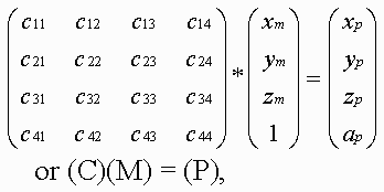 where (C) is the transformation matrix; (M) are the homogeneous coordinates of the point of the space M; (P) are the coordinates at P corresponding by the mapping. Within the scope of projective geometry, a theorem is proved that the projective mapping of the space M to the space P is unambiguously defined by specifying five pairs of points corresponding by the mapping provided that from five points specified in the space M none four points are in the same plane. Let us choose five pairs of such reference points (Mi) and (Pi) (the upper index corresponds to the number of pair) and compose the set of equations: where i = [1,...,5], r1, r2, r3 and r4 are the unknown factors; r5=1. Solving these equations, find the coefficients of the projective transformation matrix (C) used further to transform the bounding volumes. 5.3 Rendering techniqueIn this paper we used the recursive multilevel ray casting algorithm [19], which performs efficient search ray intersections with bounding volumes. At the first step of recursion, the initial viewing pyramid is divided into four smaller subpyramids in the screen plane. At the stage of division of space along the quaternary tree, 2-times compression and transfer by ±1 along two coordinates are performed: 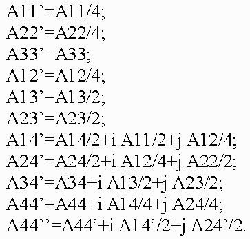 If in the equation of quadric Q(x, y, z) = 0 the values of the variables x, y, z vary within the length [-1, 1], then  We should note that if |A44| <= max[ |Q(x, y, z) – A44| ] <= maxF, then, probably, a point M0 = (x0, y0, z0) ( -1 < x0, y0, z0 < 1 ) exists such that Q(x0, y0, z0) = 0. If maxF < |A44|, then such points do not knowingly exist, and the sign of the coefficient A44 distinguishes location of the pyramid inside or outside with respect to the quadric surface Q=0 (if A44 >= 0, then the subpyramid is inside the quadric). Using results of this test, we perform division of subpyramids that fall within the quadric completely or, probably, partially, and the knowingly external subpyramids are eliminated from processing. A test for intersection of subpyramids with torus is somewhat different. For the basic quadric the test for intersection looks as follows:  Here R is the maximum perturbation function on the current interval; Aij - are the coefficients of quadratic function. The following test is performed for the perturbation function:  where Aij - are the coefficients of the quadratic perturbation function, and a value of R is additionally calculated and added to the basic function. If the intersection is determined, then the subpyramid is subject to the next recursion level. Subpyramids that do not intersect with the object are not subject to further immersion to recursion, this corresponds to elimination from consideration of square screen spaces which the subpyramid (and, consequently, the object surface) is not mapped to. The viewing pyramid is subdivided until reaching the maximal set level of recursion. The technique has an advantage that it allows discard of large parts of empty space at an early stage. Masking is used during traverse of the tree in the case of opaque objects. The multilevel ray casting technique allows us to determine effectively and quickly belonging of rays of different levels (pyramids) to bounding volumes, and discard space regions outside the objects. RMLRCA solves a tasks of Volatile and Permanent Clusters (Sherstyuk) and a tasks of Collision Detection very effectively. The key idea of the method is to keep the surface equation in polinomial form, so it may be solved quickly during the ray/surface intersection test. Weierstrass's theorem states that any continuous function f may be approximated an a closed interval by a polynomial p as closely as required. In our case, the interval [t1,t2] is obtained via intersecting the ray with the bounding volume of the function f (quadrics such as spheres and cylinders, torus, slab and so on). The initial interval [t1,t2], obtained via intersecting the ray with the bounding volume, is divided at the midpoint tmid. All equations necessary solved for sub-intervals [t1,tmid] and [tmid,t2] produce a piecewise representation of the function f over interval [t1,t2] that satisfy the requirements listed above: it is of low-degree, C#-continuous and computationally efficient. The resulting intervals t1 and t2 define the geometric location along the ray where the field is considered non-zero. Next, for each interval ti, the corresponding field function fi, is interpolated by polynomials pi. Finnaly, all intervals ti are intersected and sorted along the ray, yielding a sequence t1,t2,t3 and so on. Thus, first, the ray is intersected with the bounding volumes of all modeling functions fi. At this point, the algorithm is ready to proceed with the root-finding. The isosurface equations are built and solved for roots t in all intervals. In general, the number of roots per intervalmay be as high as the highest degree of all interpolating polynomials pi(t) defined over this interval. These roots may also occur outside this interval. Therefore, for each interval, the algorithm validates all roots by checking if they belong to the interval. While visualizing the surfaces a test is verified for belonging of only intersected points, external and internal space is discarded. To improve imaging realism and extend the class of objects imaged (translucent structures with internal density distribution, 3-D textures), it is necessary to image the internal translucent object structure. For this purpose, not only points lying on the surface but also points inside the object must participate in imaging. Therefore, while dividing the volume the internal object parts are not discarded, for them algorithm recursion is performed further. Scanning of the scene along the Z-coordinate, which corresponds to scanning of the volume through the depth, is not interrupted upon meeting the surface but is continued until the volume is scanned completely or a certain value of transparency higher than a threshold value is stored. To reduce the computation time the algorithm is adapted to quick passage of homogeneous spaces of objects, for which it is unnecessary to scan the volume completely reaching the last recursion level, it is necessary to "skip" empty or homogeneous spaces along the Z-coordinate and immediately calculate the color and the total transparency. Since ray passage through empty space makes no contribution to the final image, then the skip of the empty space is able to make the processing substantially fast and does not affect the image quality. 5.3.1 Color calculationCalculation of all color components of a pixel is performed in the same manner by the following formula:  where "ambi" refers to characteristics of ambient light, whereas "diff" and "spec" refer to the diffused and specular components of reflected light, respectively; C are the color components; Q are the weight coefficients. Color components are calculated by a vector light model. Four vectors are involved in the calculation: normal to the surface (n), vector to the light source (l), reflected light direction (r) and vector to the viewer (v): Clite - is the light source color; Csurf - is the surface color; p - is the coefficient of surface irregularity. While modeling the light transmittance through translucent media we may disregard the reflection and attenuation of reflected beams in order to reduce the amount of calculation. When only the reflection and attenuation of light remain in the path from the object to viewer - eye, the formula used to calculate the pixel color can be written as follows: where In order to allow for perspective, we must make a correction in the algorithm of color accumulation in pixel. The fact is that as a result of transformation of geometric primitives the voxel sizes become dependent on the Z-coordinate, that is why converting the color in the pixel we must also convert the transparency of voxel making correction for the change in its length. 6. ConclusionOur investigation in the volume-oriented visualization technology have made it possible to reveal some advantages in both the scene representation technique and the rendering algorithm oriented to real-time implementation. The main merits of our approach are the following:
All these merits of our approach form the ground for creating a new class of computer visualization systems for various applications. Preliminary estimates have shown that for implementation of the systems it is desirable to develop two custom VLSIs integrating about 20 millions of transistors. The system is characterized by a high parallelism, homogeneity, and vectorization of computation. The proposed algorithm of rastering along with the possibility to visualize convolution surfaces and inhomogeneous volume spaces offers a wide scope of application. This method of visualization may be easy incorporated into Voxel-Volumes project [20]. Sample images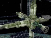 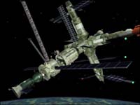 Space station  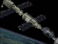 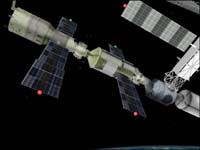 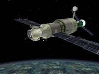 International space station 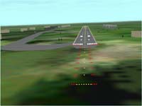 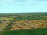 Airport 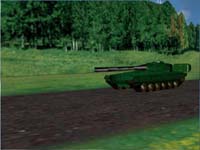 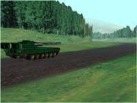 Tank
References
Write a comment below. No registration needed!
|
Platform · Video · Multimedia · Mobile · Other || About us & Privacy policy · Twitter · Facebook Copyright © Byrds Research & Publishing, Ltd., 1997–2011. All rights reserved. |