| « | » |
Very Large Capacitors
Variations on a theme: "Very Many Capacitors", "Very Large Capacity" (the spelling is preserved to render the entire range of emotions: capital letters and the mandatory "very" at the beginning). I have to disappoint you, my dear readers, that in general this parameter, cherished so much by many "lamers" (as well as by shop assistants...), means nothing. That is all these "veries" can indicate really increased reliability and safety margin of power circuits or the fact that R&D engineers (remember the southbridge cooling chapter, Delusion 2) overlooked something in motherboard design and post factum had to quickly correct their own glitches. Correcting layout flaws by stuffing large capacitors everywhere possible is not a new method, it's used in motherboard design too often. Our favourite chinese friends often make the same mistake when they copy brand layouts. It's not difficult to copy a layout, but populating a PCB with components of a proper quality is too expensive. So the quality is compensated by quantity...
I repeat: the number and capacitance of on-board capacitors by themselves don't add up to much. "Is it good or bad?!" cry out readers confused by my turn-up. You see, the idea of this chapter is to explain that "it" cannot be a significant sign. That is you shouldn't pay much attention to this motherboard characteristic. Too many reefs. A lot of large capacitors for a well-designed motherboard (where appropriate!) seem a good thing (according to the "store is no sore" principle). But well-designed motherboards will do fine even without them, that's the irony ;). A lot of capacitors in a badly-designed motherboard are practically a must. But no one guarantees that there are no bad motherboards with few capacitors. So we reverted to the point we started from...
Empirical info: a lot of capacitors (compared to other motherboards based on the same chipset with similar functionality), scattered more or less evenly across the board instead of compact groups in certain places – these are sure signs of a clumsy layout in most cases. I repeat: in most cases, but not always.
Power supply issues
We currently have four standards for power connectors on a motherboard:
- Regular 20-pin single ATX connector.
- 20-pin ATX + 4-pin 12V.
- 20-pin ATX + 4-pin 12V + 6-pin AUX connector.
- 24-pin ATX connector + 4-pin 12V connector.
- 24-pin ATX connector + 8-pin EPS12V connector.
Type 1 came with the appearance of ATX and survived till the first systems with Pentium 4 processors. Type 3 first appeared in Pentium 4 systems, but then it gradually shrank to Type 2. Type 4 appeared with the motherboards for Pentium 4 / Socket 775. Type 5 came from servers, but some desktop motherboards are now equipped with such connectors as well. Below is a table with three columns: requirements, "good" (wishes), and "bad". Motherboard evaluation method is very simple: if its power connectors satisfy the requirements, it's just normal. If the combination of connectors meets the wishes, that's good. If the combination of connectors is as specified in the "bad" column, it's potentially a problem motherboard.
| Socket A
|
|||
| Socket 423
|
|||
| Socket 478
|
|||
| Socket 754
|
|||
| Socket 939/940
|
|||
| Socket 775
|
What does "bad" mean in this case? It means that the motherboard may have problems with top processors for this socket. What does "good" mean? It means that designers paid more attention to power supply, which will probably increase the safely margin of the motherboard (though compliance with the norms should be enough for standard modes).
Sometimes motherboards also have additional power connectors for peripheral devices (for a regular plug, like for hard disks, optical drives, etc). As a rule, it helps compensate for the lack of 4-pin 12V connector on a motherboard or for the lack of the corresponding connector on an old power supply unit. In general, it's certainly "better than nothing", but you should understand that an old power supply unit may just fail to provide enough power for a new motherboard with a processor, and its power capacity will not grow with the increased number of connections...
Voltage regulators
And now let's discuss again the "N-phase" voltage regulators. For some unknown reason there exists an opinion that true gurus can find out the number of VRM channels on a motherboard in no time, just a lazy glance at it is enough. I have to confess that I'm no guru and sometimes I fall into a much longer reverie. In fact there may be bus voltage regulators (AGP, PCI Express, etc) located close to VRM. Besides, each channel can have from one to three (and maybe even four...) MOSFETs. Thus, this is no trivial task. Below I describe my method.
"Figure out" the number of the largest identical chokes (see Photos 9,10) in the CPU socket area (usually on the back of the motherboard). They may be surrounded by other chokes (looking different and usually smaller), which shouldn't be taken into account. Theoretically, the number of chokes on a motherboard indicates how many phases the on-board voltage regulator has. You can check the answer by calculating MOSFETs, which "visually belong" to these chokes. Their number must be divisible into the choke number. One can fail to determine the number of on-board voltage regulator phases correctly only when several chokes are used for a single phase or when there are nearby chokes, which have nothing to do with VRM channels. Unlike false gurus, we should be aware that it's quite possible.
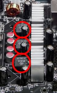
Photo 9. The chokes are somewhat unusual, but we can guess
an honest 3-phase voltage regulator with MOSFETs under cooling.

Photo 10. 4-phase voltage regulator with MOSFETs under no cooling.
But each channel has two of them.

Photo 11. A more complex situation: four identical chokes,
but that's obviously a 3-phase voltage regulator – see the three MOSFET pairs.
However (as you may have already guessed) you cannot say that "a motherboard with a 4-phase VRM is cool while a 3-phase VRM is so-so...". Because (you might have already guessed what I'll say) a good 3-phase voltage regulator with powerful and well-cooled MOSFETs may be better than a 4-phase voltage regulator with weak hot MOSFETs. Theoretically, the more channels, the better. In practice everything depends on the design quality. I'm so boring, ain't I? Well, that's me... However, to give you some evaluation criterion, I can say that a 2-phase voltage regulator on a modern motherboard (Socket 478/775/754/939/940) would spook me (though it has more to do with emotions). A 3-phase voltage regulator will not surprise me. A 4-phase one is a standard.
Besides, I know a company (only one so far), which includes additional VRM modules (to be inserted into a special connector) into some motherboard bundles – Gigabyte. Such a motherboard has been working in standard mode without external VRM for several months already. There are no complaints. Conclusion? It may be necessary only to overclockers. I'm not going to write an article how to choose a motherboard for overclockers. Never. On principle: I don't sell "Herbalife" or fake medicines and I don't recommend overclocking. That's my personal position in life. That comes from my personal experience and costly mistakes...

Photo 12. External VRM.
...No use,
but no harm either...
| « | » |
February 1, 2004
[an error occurred while processing this directive]