| 3 | 4 |
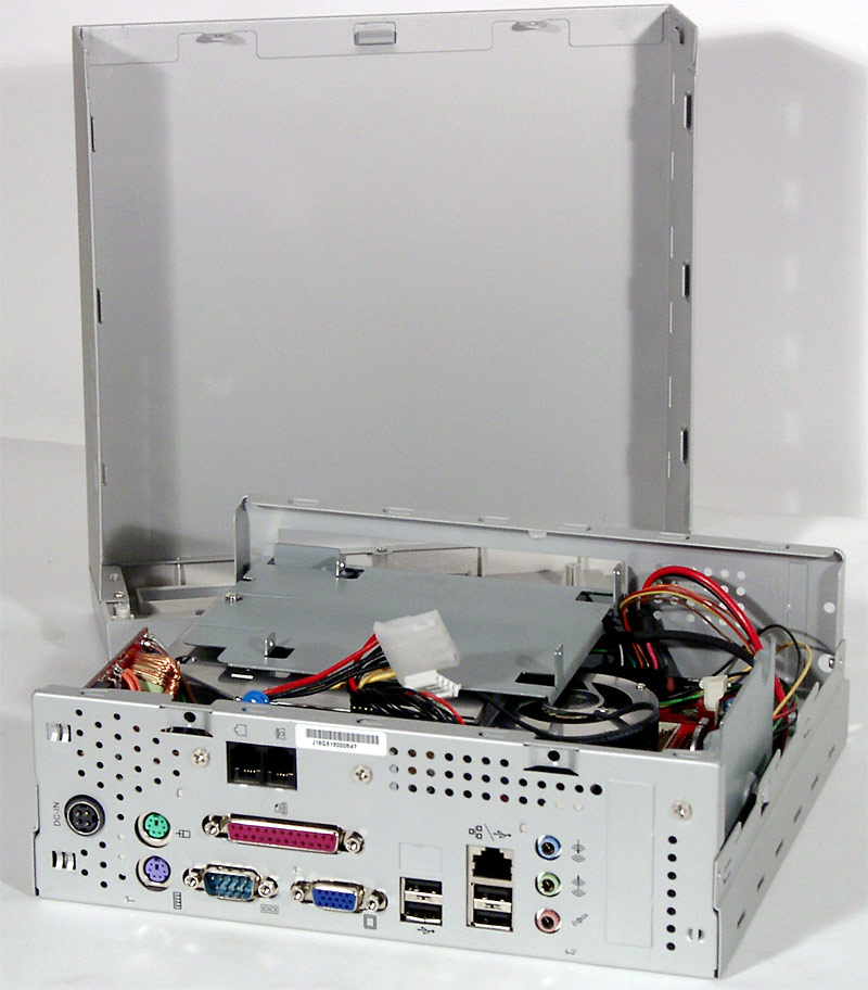
To remove the lid together with the front panel attached to it, unscrew the two screws on the rear panel. As usual, you have to get prepared for the worst, because the lack of extra space turns the innards of the barebone into a mess of cards and cables. At least, at first sight.
The disk storage devices will be accessible right after the lid is removed: the optical drive is mounted horizontally, as we have already seen, on a special additional system case support. The hard disk is installed vertically, it is mounted by two screws to the support, which you can see on the right photo, close to the case wall. Note that both notebook storage devices use a special connector (adapters are included into the bundle) and the power connector is not standard either (the bundle includes a power adapter for a hard disk and a CD/DVD drive is powered from the FDD cable).
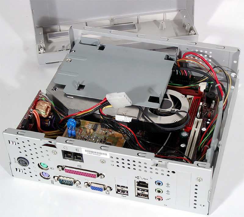
Of course it's silly to speak about the convenience of laying cables in this tiny system case, especially when you install an expansion card into the PCI slot. The situation is even worse with the connectors for the cables to the front panel being located on the mainboard closer to the rear panel. So, you have to accept that when you need to upgrade the system configuration, you'll have to remove the main internal modules and then thoroughly lay the cables once again. On the other hand, in case of office usage of U-Buddie, its upgrade urgency will be minimal.
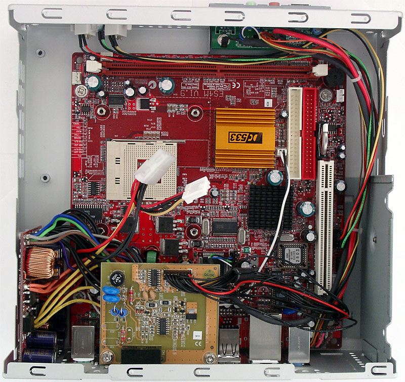
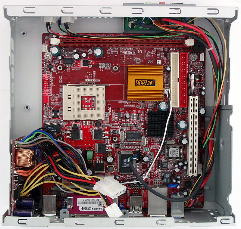
However, to reach a memory module (the mainboard contains only one DIMM slot), you only have to remove the CD/DVD drive cage. Unfortunately, the CPU cooler partially overhangs the IDE slots, so to access them you'll have to unmount the cooler. An optional card of the MC'97-modem (56K) is mounted on the rear panel of the system case, which contributes to the cable mess.

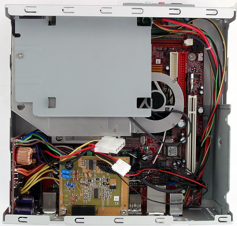
On the left there is a power converter board mounted vertically, which has all necessary power connectors (including an additional 4-pin power connector for +12 V), but nothing more. However, the only (merely physical) opportunity to expand the system functionality is to use a low-profile PCI-card, and such models do not require additional power supply (at least I don't know about such cases).
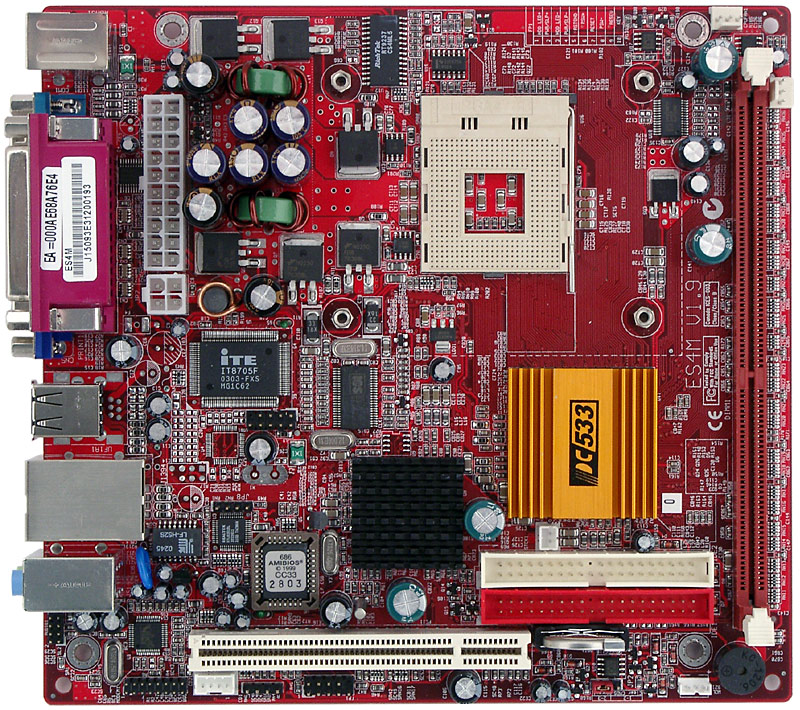
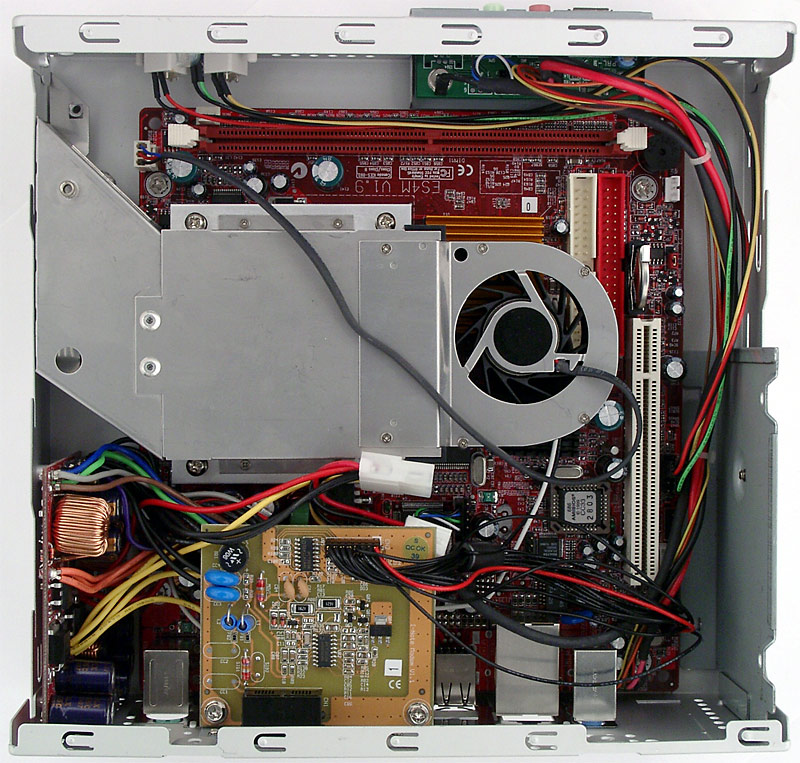
You could have already formed a picture of the functionality provided by the mainboard, which is the base of this barebone, by its connectors. Note that there are several models in the U-Buddie series with three main variations – for Celeron/Pentium 4 (Socket 478), for Duron/Athlon XP (Socket A), and for C3/Celeron/Pentium III (Socket 370). In two latter cases the mainboards come shipped with CPUs already soldered in, which reduces the price of the end solution as well as its attraction for some groups of users. Our sample modification is 4m23 with "free" Socket 478, which mainboard (ECS ES4M) is based on the chipset combination SiS650GL+SiS962L. Of course, you cannot install a top Pentium 4 processor on this mainboard, but is it really necessary to all users? The chipset supports the 533 MHz FSB frequency, though unofficially, so U-Buddie 4m23 is claimed to support processors up to Pentium 4 2.66 GHz (except for those based on Prescott core). Frequency constraint is obviously dictated by the capacity of the external power supply unit as well as by the care about the thermal conditions in the system.
These are the mainboard characteristics defined by the chipset: support for Intel Pentium 4/Celeron processors with the FSB of up to 533 MHz (with the clock frequency less than 2.66 GHz), up to 512 MB DDR200/266 (one module), integrated video core of the SiS315 chipset, 2 UATA133 channels for 4 devices, 6 USB 2.0 ports (5 laid out ones), 10/100 Mbit/sec Fast Ethernet (the PCB incorporates the Realtek RTL8201BL PHY-controller) and 4-channel audio (AC'97 C-Media CMI9738 codec). Note that some U-Buddie models may use the SiS962 southbridge with FireWire support – in this case one connector is placed on the slightly modified front panel, and the other one - on the rear panel, where the corresponding hole is bracketed in our model. There are no overclocking options in ES4M – in BIOS Setup you can only select frequencies (100/133 MHz) and memory timings (extremely poor range), as well as the FSB frequency – 100/133 MHz.
We've been steadily getting improbably bad results in our audio quality tests
of the integrated audio solution, so we publish our results as they
are – unfortunately we had no time to correct the mistake (if
it is really our mistake). The integrated audio quality was tested
in 16bit, 44 kHz using the RightMark
Audio Analyzer 5.2 test application and the Terratec
DMX 6fire sound card:
| FR passband ripple (from 40 Hz to 15 kHz), dB: |
|
|
| Noise level, dB (A): |
|
|
| Dynamic range, dB (A): |
|
|
| THD, %: |
|
|
| Intermodulation distortions, %: |
|
|
| Channel crosstalk, dB: |
|
|
General performance: Average.
| 3 | 4 |
|
|
Sergei Pikalov (peek@ixbt.com) Dmitry Majorov (destrax@ixbt.com) September 13, 2004 |